
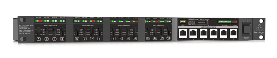
While reverse engineering the Behringer P16-I I’ve found a nice thing: this devices has 32 individual LEDs at the front to display the audio-level and the clipping of a channel. But from the internal FPGA only three lines are connected to the front-leds. So I hooked up an oscilloscope and found out, that the signal looked very like an I2S connection. The brightness of each LED corresponded with an individual bit of the 16-bit stereo I2S signal.
As a single bit cannot transport information for a pulsewidth-modulation, it turned out, that the Behringer guys uses a PDM, a pulse-density-modulation, to control the brightness of the LEDs. So I’ve implemented my own LED-controller that multiplexes all 32 LED signals into an I2S stream with a 1.536 MHz bitclock, a 48kHz frame-sync and 16 bits for “left” and “right” resulting in 32 individual bits.
Each Sigma-Delta-Modulator expects a 8-bit signal as reference. The signals look like this, when feeding the block with a sine-wave between 0 and 255. The input-signal is the upper signal, the internal accumulator the signal in the middle and the signal at the bottom is the digital output of the modulator:

In plain C-code the modulator would look like this
int16_t input;
int16_t feedback = 0;
int16_t accumulator = 0;
bool output = false;

accumulator = accumulator + input - feedback;

if (accumulator > 255) {
	output = true;
	feedback = 255;
}else{
	output = false;
	feedback = 0;
}
Next to the clock signals, the following VHDL-block expects 16 individual 8-bit brightness-values that will be fed into the first-order sigma-delta modulator. The outputs of all SDMs are then stored as individual bits into the output-shift register to be sent as regular I2S-data:
-- 32-channel LED-PDM-Controller
-- Christian Noeding, christian@noeding-online.de
-- https://chrisdevblog.com | https://github.com/xn--nding-jua
--
-- Released under GNU General Public License v3

library ieee;
use ieee.std_logic_1164.all;
use ieee.numeric_std.all;

entity led_pdm_controller is
	generic (
		bit_width : integer := 8	-- depth of the PWM/PDM
	);
	port (
		bclk			: in std_logic;
		fsync			: in std_logic;
		led1_in		: in std_logic_vector(bit_width - 1 downto 0);
		led2_in		: in std_logic_vector(bit_width - 1 downto 0);
		led3_in		: in std_logic_vector(bit_width - 1 downto 0);
		led4_in		: in std_logic_vector(bit_width - 1 downto 0);
		led5_in		: in std_logic_vector(bit_width - 1 downto 0);
		led6_in		: in std_logic_vector(bit_width - 1 downto 0);
		led7_in		: in std_logic_vector(bit_width - 1 downto 0);
		led8_in		: in std_logic_vector(bit_width - 1 downto 0);
		led9_in		: in std_logic_vector(bit_width - 1 downto 0);
		led10_in		: in std_logic_vector(bit_width - 1 downto 0);
		led11_in		: in std_logic_vector(bit_width - 1 downto 0);
		led12_in		: in std_logic_vector(bit_width - 1 downto 0);
		led13_in		: in std_logic_vector(bit_width - 1 downto 0);
		led14_in		: in std_logic_vector(bit_width - 1 downto 0);
		led15_in		: in std_logic_vector(bit_width - 1 downto 0);
		led16_in		: in std_logic_vector(bit_width - 1 downto 0);
		reset			: in std_logic;
		data_out		: out std_logic	-- I2S-like signal containing 16 bits with each a PDM
	);
end led_pdm_controller;

architecture rtl of led_pdm_controller is
	-- signals for input
	type led_array_t is array (0 to 15) of std_logic_vector(bit_width - 1 downto 0);
	signal led_input_array : led_array_t;

	-- signals for I2S output
	signal zfsync			: std_logic;
	signal channel_count	: integer range 0 to 15 := 0;
	signal led_green		: std_logic := '1';

	-- signals for sigma-delta-modulator (PDM)
	type accum_array_t is array (0 to 15) of signed(bit_width + 1 downto 0);
	signal accumulator : accum_array_t := (others => (others => '0'));
	signal feedback	 : accum_array_t := (others => (others => '0'));
	signal pdm_out     : std_logic_vector(15 downto 0);
begin
	led_input_array <= (led1_in, led2_in, led3_in, led4_in, led5_in, led6_in, led7_in, led8_in, led9_in, led10_in, led11_in, led12_in, led13_in, led14_in, led15_in, led16_in);

	process(bclk)
	begin
		if rising_edge(bclk) then
			if reset = '1' then
				-- reset internal signals
				accumulator <= (others => (others => '0'));
				feedback <= (others => (others => '0'));
				pdm_out <= (others => '0');
				led_green <= '1';
			else
				if (fsync = '1' and zfsync = '0') then
					-- first edge of bit-clock after rising LR-clock

					-- reset bitcounter
					channel_count <= 1; -- we start with one channel offset
					led_green <= '1';

					-- Calculate 16-channel First-Order Sigma-Delta Modulator (PDM) every 10.42us (96kHz) resulting in a 1kHz resolution for the LEDs
					-- =============================================
					-- C-Code for First-Order Sigma-Delta Modulator
					-- ---------------------------------------------
					--	accumulator = accumulator + input - feedback;
					--
					--	if (accumulator >= 255) {
					--		output = 1;
					--		feedback = 255;
					--	}else{
					--		output = 0;
					--		feedback = 0;
					--	}
					-- =============================================

					for i in 0 to 15 loop
						accumulator(i) <= accumulator(i) + signed(resize(unsigned(led_input_array(i)), bit_width + 2)) - feedback(i);

						-- here accumulator(i) will be used from previous step, but should be fine for an LED
						if (accumulator(i) > to_signed(2**(bit_width) - 1, bit_width + 1)) then
							pdm_out(i) <= '1';
							feedback(i) <= to_signed(2**(bit_width) - 1, bit_width + 2);
						else
							pdm_out(i) <= '0';
							feedback(i) <= to_signed(0, bit_width + 2);
						end if;
					end loop;
				else
					-- regular rising edge of bit-clock

					if (led_green = '1') then
						-- next LED is red of same channel
						led_green <= '0';
					else
						-- increase to next channel
						if (channel_count < 15) then
							channel_count <= channel_count + 1;
						else
							channel_count <= 0;
						end if;

						-- next LED is green
						led_green <= '1';
					end if;
				end if;

				zfsync <= fsync;
			end if;
		end if;
	end process;

	-- output data on every falling edge
	process(bclk)
	begin
		if rising_edge(bclk) then
			if (led_green = '1') then
				-- green LED on channel "channel_count"
				data_out <= pdm_out(pdm_out'left - channel_count);
			else
				-- red LED on channel "channel_count + 1"

				-- if LED-brightness-value is above 248 (0b11111000) this corresponds to
				-- 0b011111000000000000000000 audio-data, which means only less than 4.5dBfs
				-- headroom. So we enable the CLIP-LED
				if (unsigned(led_input_array(15 - channel_count - 1)) > 248) then
					data_out <= '1';
				else
					data_out <= '0';
				end if;
			end if;
		end if;
	end process;
end rtl;