
FPGAs are quite fast and can switch up to 200 or even more MHz. But when it comes to PWM we have a problem: even at high clocks we cannot create a high resolution as with increasing bits of the digital signal (24 bit audio for instance) we would need a clock above 1 GHz to create a PWM with sufficient resolution.
The solution is to use a noiseshaping algorithm to reduce the audio-resolution from 24-bit down to a resolution our PWM can handle with the maximum FPGA-clock we can achieve.
So first lets have a look at the PWM implementation. This is an implementation from GitHub made by the Youtuber YetAnotherElectronicsChannel. When dealing with 48kHz audio, we have only 20.83µs to calculate the PWM until a new sample reaches us. With a 200 MHz clock we need 5 nanoseconds for each step in the logic. When using a 12 bit PWM, we need 2^12 = 4096 steps, each with 5 ns resulting in 20.48µs which is very close to the 20.83µs that we have available for processing. So we have to use a noise-shaper, that reduces the audio-resolution from 24-bit down to 12 or even 11 bit. But first the PWM implementation itself:
----------------------------------------------------------------------------------
-- Original File: https://github.com/YetAnotherElectronicsChannel/FPGA-Class-D-Amplifier/blob/master/PWM_Modulator.vhd
-- Engineer: github.com/YetAnotherElectronicsChannel
----------------------------------------------------------------------------------

library IEEE;
use IEEE.STD_LOGIC_1164.ALL;
use ieee.numeric_std.all;

entity PWM_Modulator is
	generic(
		bit_width	: natural range 1 to 24 := 11
	);
	port(
		 pwmclk     : in std_logic;

		 sample_in  : in signed (bit_width - 1 downto 0);
		 sync_in    : in std_logic;

		 pwm        : out std_logic := '0'
	);
end PWM_Modulator;

architecture Behavioral of PWM_Modulator is
	signal timer : unsigned(bit_width - 1 downto 0) := (others=>'0');
	signal dir_counter : std_logic:= '0';
	signal vld_edge_detect : std_logic_vector (1 downto 0) := (others=>'0');
	signal threshold : unsigned(bit_width - 1 downto 0) := (others=>'0');
	signal data_in : unsigned(bit_width - 1 downto 0) := (others=>'0');
	signal pwm : std_logic:= '0';
	signal glitch_filt : std_logic_vector (2 downto 0) := (others=>'0');
begin
	data_in <= unsigned(std_logic_vector(sample_in));
	pwm <= '1' when timer < threshold else '0';

	process(pwmclk)
	begin
		if (rising_edge(pwmclk)) then

			vld_edge_detect <= vld_edge_detect(0) & sync_in;
			glitch_filt <= glitch_filt(1 downto 0) & pwm;

			--avoid glitches for 100% und 0% duty-cycle
			if (glitch_filt = "111") then
				pwm <= '1';
			elsif (glitch_filt = "000") then
				pwm <= '0';
			end if;

			--check if valid signal was aplied and start counter by 0 if sample has arrived to get PWM modulator fully in sync with other structure
			if (vld_edge_detect = "10") then
				dir_counter <= '0';

				--invert bit(4) to get from signed value (2s complement) into linear scaled value 0..2^x-1
				threshold <= (NOT data_in(bit_width - 1))&data_in(bit_width - 2 downto 0);
				timer <= to_unsigned(0,bit_width);


				--do up and down counting from 0 to 2^x-1 and back down to 0
			elsif (timer = to_unsigned((2**bit_width)-1,bit_width) and dir_counter = '0') then
				dir_counter <= '1';
				timer <= to_unsigned((2**bit_width)-1,bit_width);

			elsif (timer = to_unsigned(0,bit_width) and dir_counter = '1') then
				dir_counter <= '0';
				timer <= to_unsigned(0,bit_width);

			elsif (dir_counter = '0') then
				timer <= timer + to_unsigned(1,bit_width);

			elsif (dir_counter = '1') then
				timer <= timer - to_unsigned(1,bit_width);
			end if;
		end if;
	end process;
end Behavioral;For the noiseshaper I’ve found a nice paper with the title “Accurate stability prediction of single-bit higher-order delta-sigma (Δ-Σ) modulators for speech codecs” (https://ieeexplore.ieee.org/document/5937891) where the authors coefficients suggested, that worked very well for me. A noise-shaper is similar to a sigma-delta-modulator and uses a higher-order. In this case I’m using a 4th-order modulator like shown in the following diagram by J. Lota et. al.:
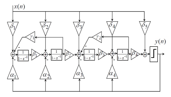
The following implementation shows a 4-th order noise-shaping algorithm:
----------------------------------------------------------------------------------
-- Original File: https://github.com/YetAnotherElectronicsChannel/FPGA-Class-D-Amplifier/blob/master/noiseshaper.vhd
-- Engineer: github.com/YetAnotherElectronicsChannel
----------------------------------------------------------------------------------

library IEEE;
use IEEE.STD_LOGIC_1164.ALL;
use ieee.numeric_std.all;

entity noiseshaper is
	generic(
		bit_width	: natural range 1 to 24 := 11
	);
	port (
		clk        : in std_logic;

		sample_in  : in signed (23 downto 0);
		sync_in    : in std_logic;

		sample_out : out signed(bit_width - 1 downto 0) := (others=>'0');
		sync_out   : out std_logic := '0';

		busy       : out std_logic := '0';
		limit      : out std_logic := '0'

		--a1 : integer := -514; -- 0.0157 * 2^15 = -514
		--a2 : integer := -4453; -- 0.1359 * 2^15 = -4453
		--a3 : integer := -16843; -- 0.5140 * 2^15 = -16843
		--a4 : integer := -11826; -- 0.3609 * 2^15 = -11826
		--b1 : integer := 514; -- 0.0157 * 2^15 = 514
		--b2 : integer := 4453; -- 0.1359 * 2^15 = 4453
		--b3 : integer := 16843; -- 0.5140 * 2^15 = 16843
		--b4 : integer := 11826; -- 0.3609 * 2^15 = 11826
		--g1 : integer := -98; -- 0.003 *  2^15 = -98
		--g2 : integer := -59  -- 0.0018 * 2^15 = -59
	 );
end noiseshaper;

architecture Behavioral of noiseshaper is
	-- summing points after each node
	signal x1 : signed(31 downto 0) := (others=>'0');
	signal x2 : signed(31 downto 0) := (others=>'0');
	signal x3 : signed(31 downto 0) := (others=>'0');
	signal x4 : signed(31 downto 0) := (others=>'0');
	signal x5 : signed(31 downto 0) := (others=>'0');

	-- delay registers for integrators
	signal x1d : signed(31 downto 0) := (others=>'0');
	signal x2d : signed(31 downto 0) := (others=>'0');
	signal x3d : signed(31 downto 0) := (others=>'0');
	signal x4d : signed(31 downto 0) := (others=>'0');
	signal x5_24b : signed(23 downto 0) := (others=>'0');
	signal state : integer := 0;

	signal sample_tmp : signed(31 downto 0) := (others=>'0');

	-- multiplier signals
	signal mul_inp_2 : signed(15 downto 0) := (others=>'0');
	signal mul_inp_1 : signed(31 downto 0) := (others=>'0');
	signal mul_result : signed(31 downto 0) := (others=>'0');

	signal a1 : integer := -514; -- 0.0157 * 2^15 = -514
	signal a2 : integer := -4453; -- 0.1359 * 2^15 = -4453
	signal a3 : integer := -16843; -- 0.5140 * 2^15 = -16843
	signal a4 : integer := -11826; -- 0.3609 * 2^15 = -11826
	signal b1 : integer := 514; -- 0.0157 * 2^15 = 514
	signal b2 : integer := 4453; -- 0.1359 * 2^15 = 4453
	signal b3 : integer := 16843; -- 0.5140 * 2^15 = 16843
	signal b4 : integer := 11826; -- 0.3609 * 2^15 = 11826
	signal g1 : integer := -1200; -- 0.003 *  2^15 = -98
	signal g2 : integer := -300;  -- 0.0018 * 2^15 = -59

	signal zero_vector : std_logic_vector(32 - 1 - 8 - bit_width downto 0) := (others => '0');
begin
	process (mul_inp_1, mul_inp_2)
	begin
		-- multiply and do right-shift by 15 (fixed-point mult with 32-bit int and q1.15 value)
		mul_result <= resize(shift_right(mul_inp_1*mul_inp_2,15),32);
	end process;

	process (clk)
	begin
		if (rising_edge(clk)) then

			-- start and calculate through the structure as shown in the block diagram in documentation-pdf file
			if (state = 0) then
				sync_out <= '0';
				busy <= '0';
				if (sync_in = '1') then
					sample_tmp <= resize(sample_in, sample_tmp'length); -- convert 24 bit to internal 32 bit
					state <= 1;
					busy <= '1';

					mul_inp_1 <= resize(sample_in, mul_inp_1'length);
					mul_inp_2 <= to_signed(b1,16);
				end if;


			elsif (state = 1) then
				x1 <= mul_result;
				state <= 2;

				mul_inp_1 <= x5;
				mul_inp_2 <= to_signed(a1,16);


			elsif (state=2) then
				x1 <= x1 + mul_result;
				state <= 3;

				mul_inp_1 <= x2;
				mul_inp_2 <= to_signed(g1,16);

			elsif (state=3) then

				x1 <= x1 + mul_result + x1d;
				mul_inp_1 <= sample_tmp;
				mul_inp_2 <= to_signed(b2,16);
				state <= 4;


			elsif (state=4) then
				x2 <= mul_result;
				state <= 5;

				mul_inp_1 <= x5;
				mul_inp_2 <= to_signed(a2,16);


			elsif (state = 5) then
				x2 <= x2 + mul_result + x2d +x1;
				state <= 6;

				mul_inp_1 <= sample_tmp;
				mul_inp_2 <= to_signed(b3,16);


			elsif (state = 6) then
				x3 <= mul_result;
				state <= 7;

				mul_inp_1 <= x5;
				mul_inp_2 <= to_signed(a3,16);

			elsif (state = 7) then
				x3 <= x3 + mul_result;
				state <= 8;

				mul_inp_1 <= x4;
				mul_inp_2 <= to_signed(g2,16);


			elsif (state = 8) then
				x3 <= x3 + mul_result + x3d + x2;
				state <= 9;

				mul_inp_1 <= sample_tmp;
				mul_inp_2 <= to_signed(b4,16);


			elsif (state = 9) then
				x4 <= mul_result;
				mul_inp_1 <= x5;
				mul_inp_2 <= to_signed(a4,16);
				state <= 10;

			elsif (state = 10) then
				x4 <= x4 + mul_result + x4d + x3;
				state <= 11;
			elsif (state = 11) then
				x5 <= x4 + sample_tmp;
				state <= 12;


			-- limit signal to maximum 2^23 and -2^23 (hence 24 bit audio)
			elsif (state = 12) then
				if (x5 > to_signed(8388607,31)) then
					x5_24b <= to_signed(8388607,24);
					limit <= '1';
				elsif (x5 < to_signed(-8388607,31))then
					x5_24b <= to_signed(-8388607,24);
					limit <= '1';
				else
					x5_24b <= resize(x5,24);
				end if;
				state <= 13;

			-- quantize signal to x bit (cut off lsb)
			elsif (state = 13) then
				 x5 <= signed(std_logic_vector(x5(31 downto (23 - bit_width + 1))) & zero_vector); -- fill with zeros so that desired bit-width fits to 32 bit
				 sample_out <= x5_24b(23 downto (23 - bit_width + 1));
				 x1d <= x1;
				 x2d <= x2;
				 x3d <= x3;
				 x4d <= x4;
				 sync_out <= '1';
				 state <= 0;
				 limit <= '0';

			end if;
		end if;
	end process;
end Behavioral;