
Table of Contents
- Calculating duty cycle for continuous current
- Discontinuos currents
- Rewriting a complex function – with complex numbers
- Testing solution 1: the short one
- Solutions 2 and 3: the heavy ones
In mid-2010s I’ve spent weeks on comparing different topologies for inverters and DC/DC-converters for PV-applications. One of these topologies was quite interesting as it had a surprise when calculating the equations for the duty cycle. Under specific circumstances this duty cycle went from a positive real value into a complex imaginary value. To understand why this can happen, lets have a look at the topology itself:
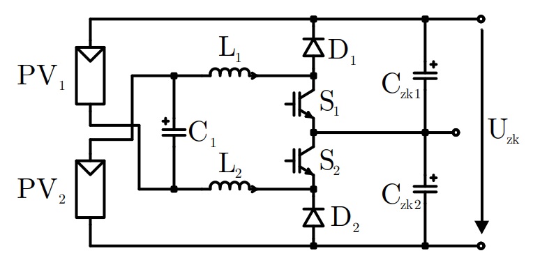
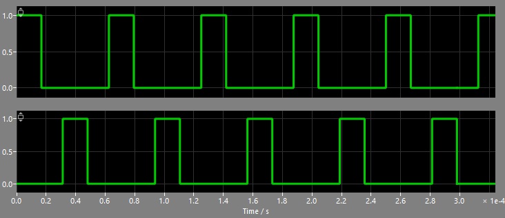
The basic idea here is, that two isolated DC-sources like two PV-panels or batteries are connected in a way, that they can be put in series or in parallel – or between when using high-frequency switches. There are two switches, that are turned on and off with a phase-shift of 180°:
As two diodes separates the DC-link from the switches, the dutycycle can be chosen between 0% resulting in the topology shown as a) in the graphics below, which is parallel-connection of the two input sources and 100% resulting in topology shown as b), which is a series-connection:
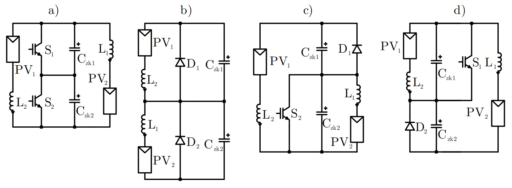
The other two options c) and d) show the state when only switch S1 or switch S2 is turned on. During these two states only one of the sources is connected to the load while the other source is connected to one of the dc-link-capacitors only.
During state “a” (full parallel-connection) the output-voltage equals the source-voltage while during state “b” (full series-connection) the output-voltage equals the sum of both sources. This allows us to select any value between 1x and 2x of the input voltage. Up to now this is not unusual and looking at the individual signals everything is fine:
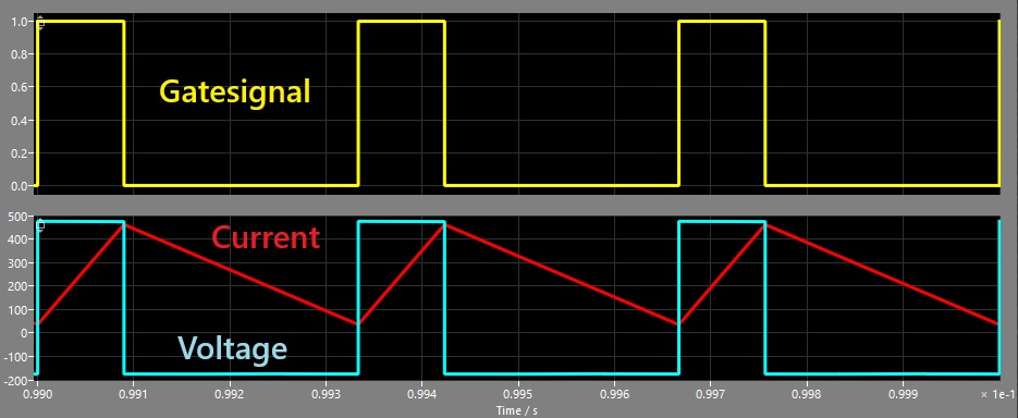
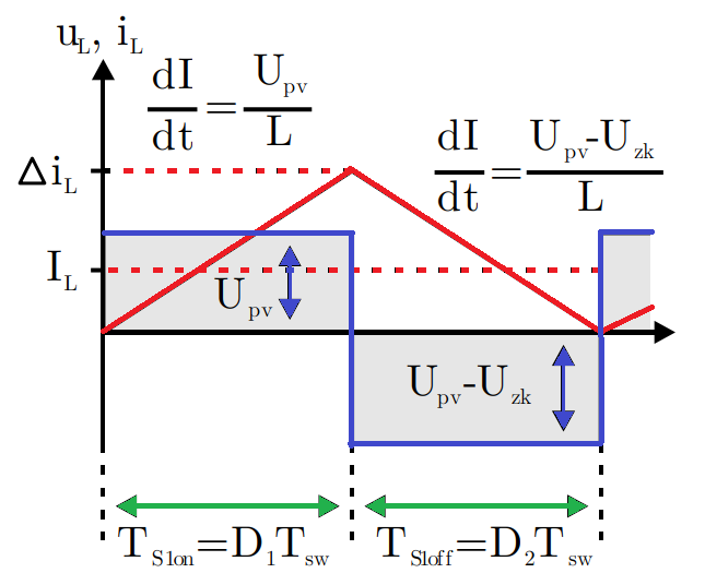
In yellow we can see the gate-signal of one of the two switches, the red-curve is the corresponding inductor-current and in blue the voltage over the inductor is shown. As the inductor-current is kept above zero, we are within the continuous-conduction-mode and we can calculate the dutycycle like this:
Calculating duty cycle for continuous current
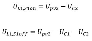
Since calculating the duty cycle was my goal, I started with the voltages of the two states: during switch S1 turned on and the other during turn-off-state:
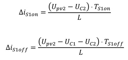
As the current is increased during the positive voltage (charging of the inductor) and decreased with negative voltage (discharging), the equations for the two currents can be written like this:
As the slope of both currents is depending on the parameters of the inductor itself, the absolute value of the slope has to be identical when we do not change the inductor during the charge or discharge. Therefore, we can equate the slopes like this:

Now we should develop the equation and try to get all parts in dependency of things we have under control (like the turn-on-time of the semiconductor):
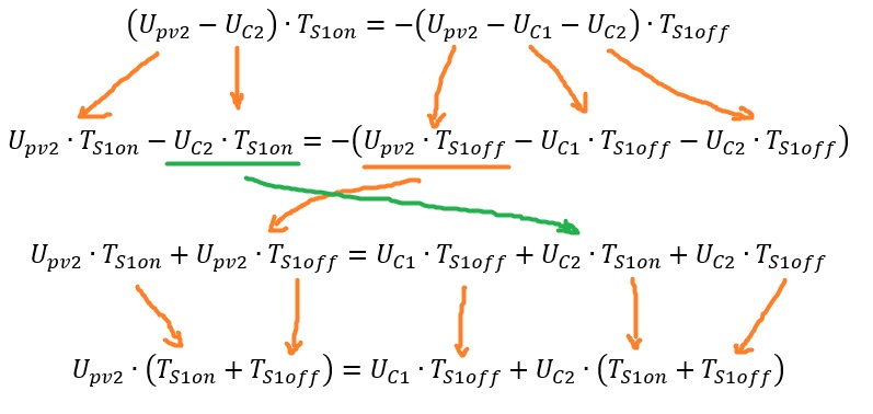
Now we can separate the variables for voltages to the left and for the time on the right side. Since the duty cycle is only the ratio of the on-time to the total period duration, we can simplify the equation even more:
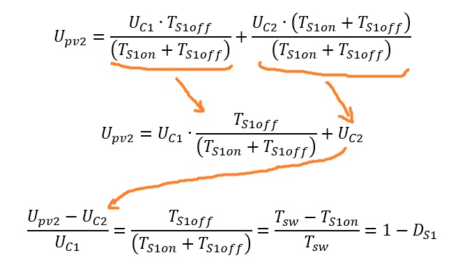
So, finally I’ve found the equation for a single switch and since this topology is symmetrical, we can write the duty cycle for both switches like this:
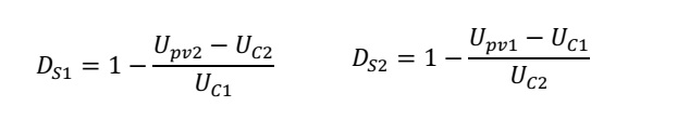
If we assume, that the voltages on both capacitors are equal and hold 50% of the total dc-link-voltage Uzk, we can simplify these equations even more:
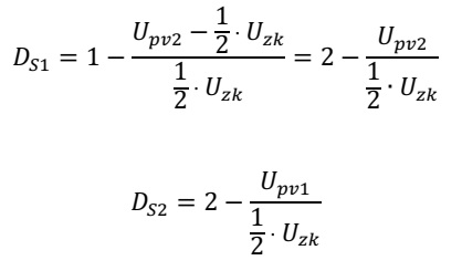
So, we’ve broken down this quite complex circuit into a nice equation for both switches. But…
Discontinuos currents
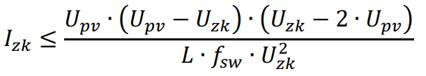
…inductor currents can get down to 0A. Power electronics engineers call this operating mode “discontinuous operation”. So far so good: 0A means no current and probably no problems. But for boost-converters – and for this special circuit here – the voltage-ratio gets non-linear in discontinuous mode, hence the equation calculated above is not valid any more. The following picture shows the duty cycle over the input-voltage under different load-conditions:

Below 50% load, the duty cycle becomes very hard to determine without further investigations. For regular buck- or boost-converters the duty cycle can be calculated quite easily. But as our system here has two inductors and – depending on the switching-states – different ways for the current, the discontinuous operation has a special case:
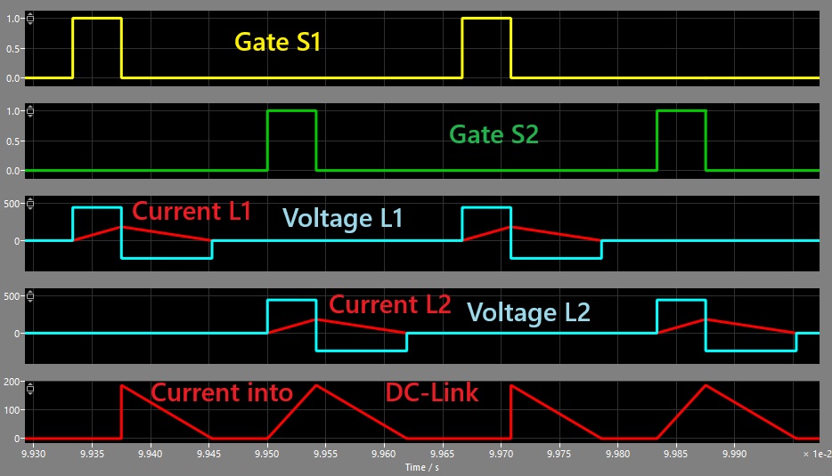
Looking at the two inductor-currents, everything seems fine, but when looking at the current into the upper DC-link, we can see that there is some kind of overlayed current with 100% current of inductor L2 and only parts of inductor L1. So I separated the total current into individual components and came up with the following parts A to D:
- A: positive current slope (charging)
- B: negative current slope (discharging)
- C: regular gap-area
- D: additional gap-area
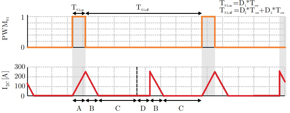
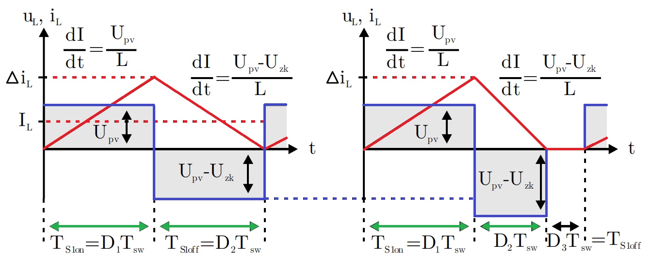
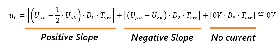
For calculating the duty cycle, only that parts of the current are important for us that are not equal to 0A and that’s connected to the switch we can control. The desired equation for the duty cycle should ensure the desired voltage-transmission ratio even when the current behaves like shown above. So lets have a look at the timing-diagram again, but now for both, continuous operation (left) and discontinuous operation (right). We have to consider part D1 for the positive slope and part D2 for the negative slope. Part D3 can be omitted for the current as it does not contribute to the energy-transfer, but it has to be taken into account regarding the timing:
To get a starting point lets calculate the mean-value of the inductor current of the converter while keeping the relevant current-parts A and B in mind:
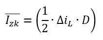
We can write the full equation for one single inductor like this:

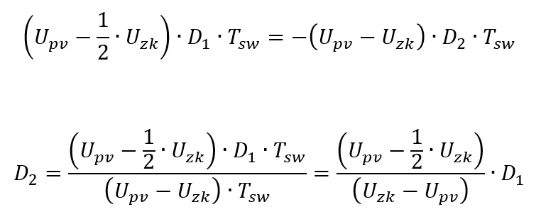
In this equation we have three dependencies: the current-ripple, which can be calculated, but two different times D1 and D2, while D3 is multiplied with 0A. Looking at the timing-diagram of a single inductor again, we can write another equation, that helps us to find an equation for D2 based on D1: the inductor-voltage
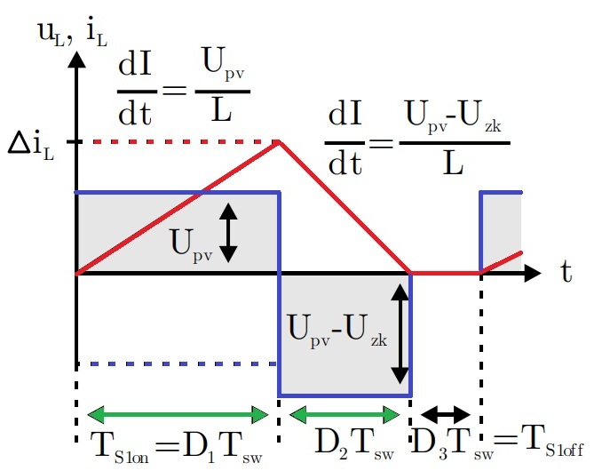
To get a circuit within steady-state, the voltage-time-area of the inductor has to be 0 Vs:
As we have two unknown variables here, we can equate the positive and negative slopes and get an equation for time D2, which is that time the inductor-current needs to reach 0A again:
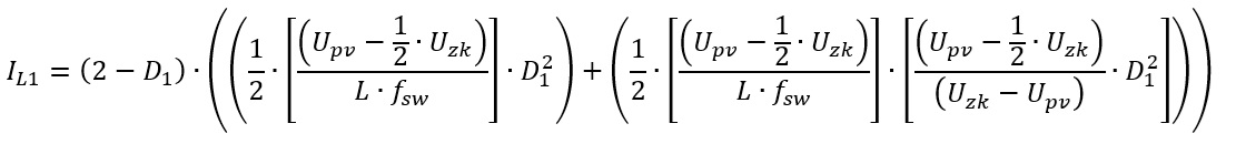
For the current-ripple we can assume, that the voltages on both capacitors Uc1 and Uc2 are the same, so we have 50% of the DC-link voltage over each of these two capacitors. So we can write the equation for the current like this:

And that’s it – more or less. At least we can calculate the mean-value of the current based on the duty cycle D1 now:

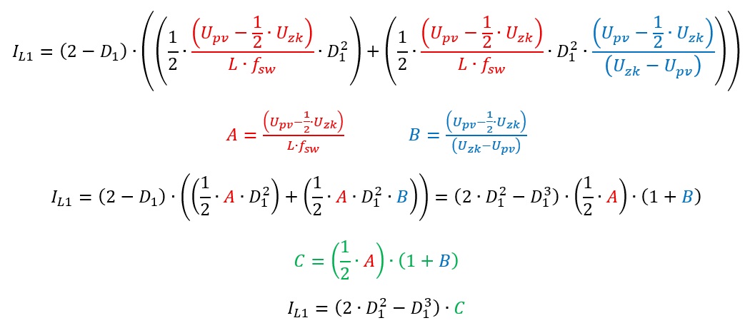
We can simplify this equation a bit:
The last thing we have to do now is rewriting this equation for D1. However, D1 is here in the third power overall, which is a bit problematic.
Rewriting a complex function – with complex numbers
OK, lets try to rewrite our function as far as possible with some substitutions of the constant expressions:
Wow, we reduced this monster to a much smaller expression. But since this is a cubic equation, there is no simple algebraic transformation to D1 as with quadratic equations. Normally, we would try to switch to numeric solutions, but as we need an equation for our duty cycle to control this circuit, we have to keep going. There are lot of engineering-tools that can be used. For me MathCAD did a really good job solving my problem. If you’re brave, click on the next picture that shows two options for the duty cycle D1:
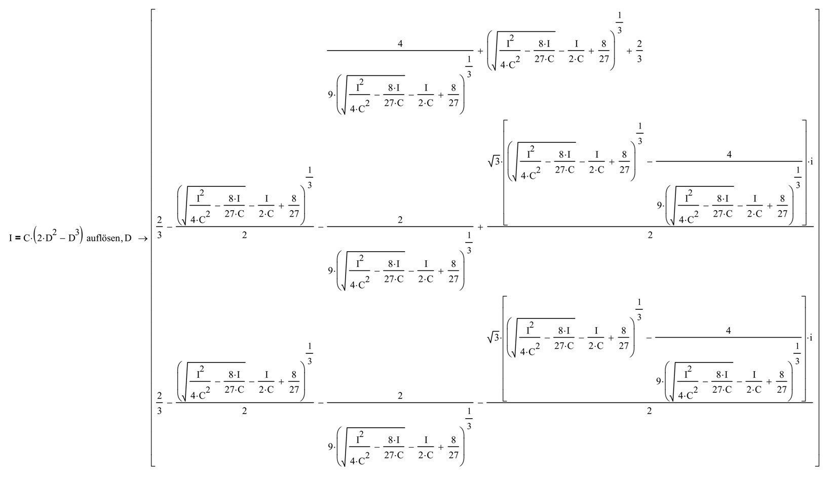
MathCAD rewrote the equation and gave us three different results, since the current is a function of the third power.
Testing solution 1: the short one
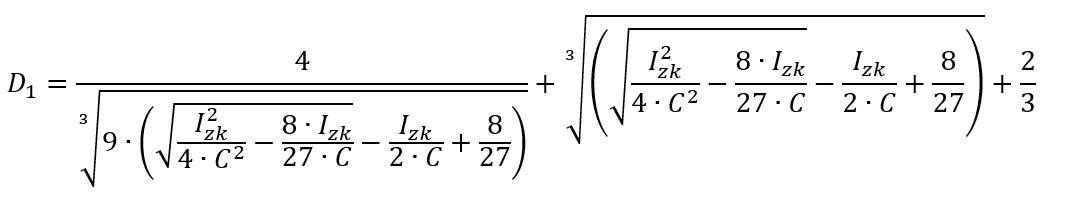
As the first solution stays within the real numbers, lets have a closer look here, first:
But that’s not the whole equation: let’s insert part A, B and C to see the first full monster-equation:
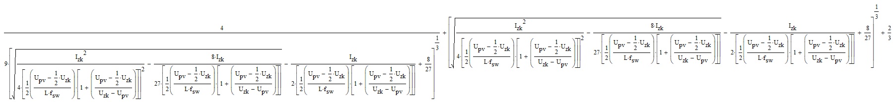
Keep in mind: that’s not some kind of theoretical analysis of something not physical – its an actual DC/DC-converter what we are looking on. So lets enter some real-world parameters to calculate our duty cycle:
- Input-Voltage Upv = 1300 V
- Output-Voltage Uzk = 1500 V
- Power = 200 kW
- Switching-Frequency: 3 kHz
- Inductor-Value: 50 µH
The calculated duty cycle resulted in D1 = 199.5%. A value above 100% is not reasonable as the semiconductor cannot be turned-on longer than the full periode of the PWM-cycle. In this circuit a duty-cycle of 100% would result in 100% series-connection of the input-sources and would result in an output-voltage of 2600V, so lets try option 2.
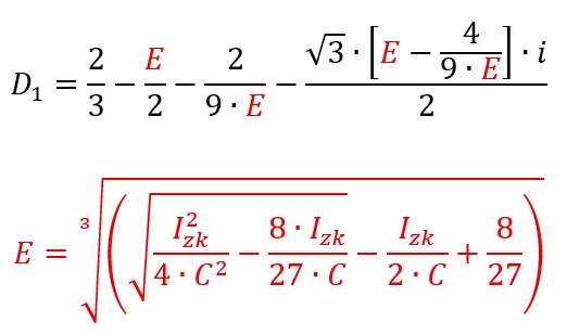
Solutions 2 and 3: the heavy ones

When inserting the same values for voltages, inductor and frequency, we get a duty cycle of -9.6% – not reasonable again as a semiconductor cannot be turned-off more than 0%. So hopefully solution 3 will give us some results we can work with. Solution 3 is very comparable to solution 2, but uses a “minus” instead of a “plus” to combine the first and second half of the equation:
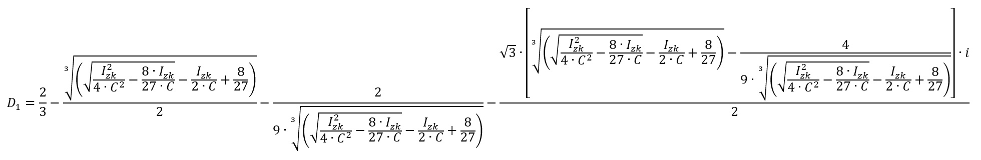
So understand this equation a bit better, lets substitude the four very similar parts of the equation:
Again, lets insert all individual parts A, B and C to get the full equation:

OK, lets get serious, this equation is totally confusing and intransparent. But it hopefully delivers a solution – lets check it and insert our real-world values again:
- Input-Voltage Upv = 1300 V
- Output-Voltage Uzk = 1500 V
- Power = 200 kW
- Switching-Frequency: 3 kHz
- Inductor-Value: 50 µH
And the calculated duty cycle resulted in D1 = 10.1% which sounds promising. Lets fire up a power-electronics simulation with these values…
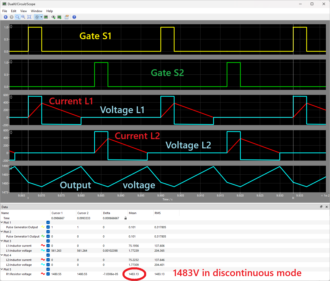
… and we are receiving 1483V even within the discontinuous mode – that’s what we want. Finally we have equations for both the continuous and the discontinuous operation of this special circuit, what a ride!
If you ponder what happens if you try to use this new equation during the continuous mode: the function will not result reasonable solutions here, as the requirement (current at 0A for a specific time) is not met. The following picture shows the discontinuous operation area within the black dotted box. On the left and right side we have continuous operation and would get imaginary components:

So we need an additional function, that checks if we are operating in continuous or discontinuous mode at a given time and select the fitting function for the duty cycle. One option is to check if the imaginary component equals 0, then use the function for the continuous duty cycle or check the actual current together with the ripple current and check if the current crosses 0A:
At the end here a try to plot the full duty cycle over all options to get an idea of the complexity of this circuit:

The final equation that works for this circuit within the discontinuous mode looks like this:

That’s it for now. Compared to the other topics on this blog, this was totally different, but dealing with complex numbers while calculating the duty cycle was also something new for me.