

Disposing of defective appliances is common practice and repairing them is often uneconomical. However, there are often still very useful components in such devices. I took a closer look at a Thermomix and found a nice motor control unit.
Thermomix
The Thermomix is a food processor from the German Vorwerk Group based in Wuppertal close to Cologne that can chop and mix food as well as heat or cool it. After a thunderstorm, a neighbor asked me if I could repair the appliance. It seemed obvious that parts of the electronics had been damaged by a mains overvoltage.

So I opened the device and measured the ohmic resistances within the DC-supply and other parts of the circuit. I identified a defective Diode (a Rohm SCS220KG) and replaced it. But a gate-driver did not behave correctly as well. So I replaced the ST L6385E high-side/low-side driver. After this parts of the DC-supply came back to life. But again, another IC showed up some issues: a ST HCF4093 NAND Schmnitt trigger… After replacing this IC too, I invested more than 15€ (shipping was quite expensive) in this old devices and decided to stop the revitalization of this device. But another component had caught my attention: the motor and its driver-circuit.
Basics of Reluctance Motors
Searching the internet for a bit more information about this device I found this:
- Model: Vorwerk Thermomix TM31
- Motor: Maintenance-free reluctance motor with 500 W rated power
- Control: Infinitely variable speed adjustment from 100-10200 revolutions per minute
- Heating: 1kW heating-system
- Cost: still around 450€ on second-hand market
So this device uses a reluctance-motor. This is neat, because this type of motor does not use any rare earths or rotors-windings but only sheets of electric metal. Another benefit of this type of motor: it does neither need a high-performance sine-wave-current nor a field-oriented control, but can be controlled only using cheap digital logic. Within the so called switched reluctance motor (SR-drive) the phase next to the rotor will be switched to the DC-supply to pull the rotor in the desired direction.
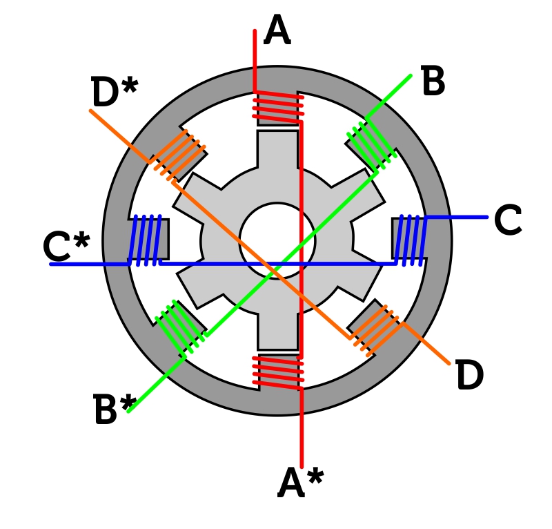
The general construction of this motor looks like the following diagram, a so called 4-phase, 8/6-pole SR-drive, as the rotor has 6 poles and the stator 8 poles:
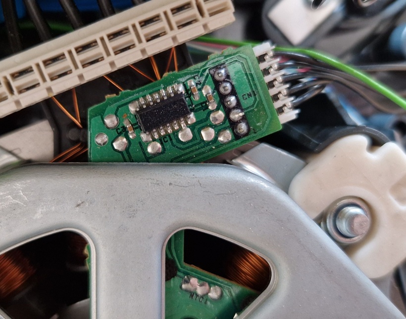
To detect the position of the rotor, hall-sensors are applied on the stator, connected to a small decoder-IC:
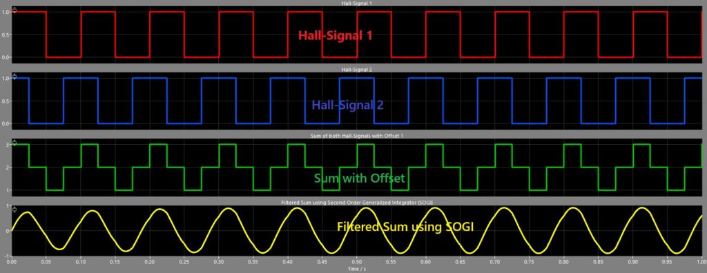
Two signals can be measured on the outputs of this Hall-signal IC: on each falling edge of signal one (red), the rotor is at position 1, on rising edge of signal 2 (blue) the rotor reaches position 2. Position 3 is on the rising edge of signal 1 and falling edge of signal 2 marks the position 4:

These signals could be processed to a much more detailed reconstruction of the rotor-position: by summing both signals, we will get a rough sine-wave (green curve in next diagram) and by applying a so called Second-Order-Generalized-Integrator (SOGI), we can create a phase-alligned signal which is related to the rotor-position:
But for this project the information about the edges of the both hall-signals are more than enough to detect the current position of the rotor.
Power Electronics
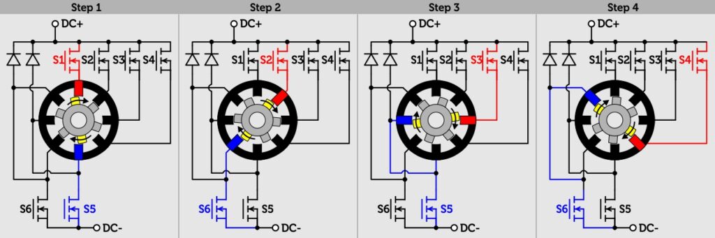
There are several possible options to control the SR-drive. Vorwerk selected a very semiconductor-saving variant and used one MOSFET per phase and additional two MOSFETs for a connection to the DC minus. So the connection of the power-electronics and the pulse-pattern looks like this:
Programming a control scheme with Arduino
Looking at the above graphics, the following pulse-pattern has to be applied:
| State | S1 | S2 | S3 | S4 | S5 | S6 |
|---|---|---|---|---|---|---|
| 1 | 1 | 0 | 0 | 0 | 1 | 0 |
| 2 | 0 | 1 | 0 | 0 | 0 | 1 |
| 3 | 0 | 0 | 1 | 0 | 1 | 0 |
| 4 | 0 | 0 | 0 | 1 | 0 | 1 |
For the hardware I’ve chosen a small Arduino Leonardo board and I connected both hall-signals to each an interrupt-input to get the current rotor-state. By tracking the time between two interrupt-service-routines, I was able to calculate the speed of the rotation as well:
void isr_pin2() {
  if (digitalRead(2)) {
    // rising edge hall-signal 1
    rotorState = 3;
    rotorReverse = !digitalRead(3);
  }else{
    // falling edge hall-signal 1
    rotorState = 1;
    rotorReverse = digitalRead(3);
  }

  // calculate speed
  periode = (micros() - timeBetweenISR) * 2;
  timeBetweenISR = micros();
}

void isr_pin3() {
  if (digitalRead(3)) {
    // rising edge hall-signal 2
    rotorState = 2;
    rotorReverse = digitalRead(2);
  }else{
    // falling edge hall-signal 2
    rotorState = 4;
    rotorReverse = !digitalRead(2);
  }
}Within the main-loop, the individual mosfets are then activated based on the detected rotor-position:
void loop() {
  if (motorRunning) {
    motorStep();
  }else{
    // turnOff all MOSFETs connected to DC+
    digitalWrite(pinS1, LOW);
    digitalWrite(pinS2, LOW);
    digitalWrite(pinS3, LOW);
    digitalWrite(pinS4, LOW);

    // turnOn all MOSFETs connected to DC-
    digitalWrite(pinS5, HIGH);
    digitalWrite(pinS6, HIGH);
  }
}

void motorStep() {
  // check if we should energize the next stator-pole or if we stay in current state
  if (micros() < nextPole) {
    return; // stay in current state
  }

  // we have to energize next pole
  if (desiredSpeed < 0) {
    // we are in reverse-mode
    if (rotorState <= 1) {
      rotorState = 4;
    }else{
      rotorState -= 1;
    }
  }else{
    // we are in forward-mode
    if (rotorState >= 4) {
      rotorState = 1;
    }else{
      rotorState += 1;
    }
  }

  // update the MOSFET-states
  digitalWrite(pinS1, (rotorState == 1) ? HIGH : LOW);
  digitalWrite(pinS2, (rotorState == 2) ? HIGH : LOW);
  digitalWrite(pinS3, (rotorState == 3) ? HIGH : LOW);
  digitalWrite(pinS4, (rotorState == 4) ? HIGH : LOW);

  digitalWrite(pinS5, ((rotorState == 1) || (rotorState == 3)) ? HIGH : LOW);
  digitalWrite(pinS6, ((rotorState == 2) || (rotorState == 4)) ? HIGH : LOW);

  // calculate time for next pole with polePairs = 4 and sequenceSteps = 4
  nextPole = micros() + (60000000.0f / abs(desiredSpeed * polePairs)) / sequenceSteps;
}Finally, within the setup-function the individual outputs have to be initialized correctly, but thats it:
void setup() {
  // set MOSFET-pins to output
  pinMode(pinS1, OUTPUT);
  pinMode(pinS2, OUTPUT);
  pinMode(pinS3, OUTPUT);
  pinMode(pinS4, OUTPUT);
  pinMode(pinS5, OUTPUT);
  pinMode(pinS6, OUTPUT);

  // connect input-pins with hall-signals to interrupts
  pinMode(2, INPUT);
  pinMode(3, INPUT);
  attachInterrupt(digitalPinToInterrupt(2), isr_pin2, CHANGE);
  attachInterrupt(digitalPinToInterrupt(3), isr_pin3, CHANGE);

  // configure motor
  polePairs = 4.0f;
  sequenceSteps = 4.0f;
  motorRunning = false;
  desiredSpeed = 100.0f; // rpm
}Results
With this small piece of code it is possible to control a full-featured motor with control over speed and left/right-rotation. Have a look on the results by your own on the following video:
The full code can be found in my GitHub repository for the Arduino Switched Reluctance Drive