
Without the possibility to adjust the volume of individual frequency bands within an audio signal, modern audio would not sound the same. Today I’d like to show how I’ve implemented a EQ within my FPGA audio-mixer.
In this blog-post I won’t describe the general idea of an EQ, because there are more capable persons available doing this, like Vesa Välimäki and Joshua Reiss with their All About Audio Equalization: Solutions and Frontiers. But I want to share with you, how I implemented an audio-filter within my Cyclone 10LP to create an EQ and crossovers.
Selecting the right filter-type
As the Cyclone 10LP of the Arduino MKR Vidor4000 is quite limited in its available logic-elements and multiplication-blocks, I searched for a solution to implement an equalizer with a low logic-demand and ressource-footprint. For audio-applications two filter-types come into question: besides the FIR-filters, infinite impulse response-filters (IIR) are using only a limited number of samples from the past, to calculate the desired result: three values for each, input and output. IIR-filters have a low latency and low calculation-demand, while FIR-filters are more stable and linear. As the reducation of ressource-demand and latency were my primary goals, I had a deeper look at the IIR-filters. To calculate this Biquad-IIR-filter (because it has two poles and two zeros), I had to create a storage for two samples of the past for each input and output. These values are then multiplied with a specific coefficient, that defines what type of filter we are creating:

The resulting difference equation that defines how the output signal is related to the input signal for a simple equalizer follows the following equation:

With these six coefficients a0…a2 and b0…b2 we can control the general behavior of the filter. The online-tool Biquad calculator v3 next to the Audio-EQ-Cookbook can be used to calculate all coefficients to form a low-pass, high-pass, peak or shelf-filter using the previous equation. To get rid of the division, the coefficients a0…a2 and b1…b2 can be divided by b0, before sending them to the FPGA.
VHDL-implementation
Now that I had chosen a fitting algorithm I had to implement these filters in VHDL. First I had to define the inputs and outputs for this EQ:
port (
    clk         : in std_logic := '0';
    sample_in   : in signed (23 downto 0) := (others=>'0'); -- audio-sample
    sync_in     : in std_logic := '0';

    sample_out  : out signed(23 downto 0) := (others=>'0'); -- audio-sample
    sync_out    : out std_logic := '0';

    -- 32-bit filter-coefficients set by microcontroller
    a0          : in signed(31 downto 0);
    a1          : in signed(31 downto 0);
    a2          : in signed(31 downto 0);
    b1          : in signed(31 downto 0);
    b2          : in signed(31 downto 0)
);As we need five multiplications of a 24-bit-sample with a coefficient with at least 32-bit for each path, we end up using already 18% of our 112 DSP-multiplicator-sections (DSP-slices) for one single EQ. To mitigate this bottleneck, the first thing was implementing a reusable multiplication-process within the FPGA:
architecture Behavioral of filter_iir is
    --signals for multiplier
    signal mult_in_a : signed(bit_width - 1 downto 0) := (others=>'0'); -- input signal
    signal mult_in_b : signed(31 downto 0) := (others=>'0'); -- coefficient
    signal mult_out : signed(bit_width + 32 - 1 downto 0):= (others=>'0');
     -- [...]
begin
    -- multiplier
    process(mult_in_a, mult_in_b)
    begin
        mult_out <= mult_in_a * mult_in_b;
    end process;

-- [...]Now that we have a single multiplication-process, that can be called several times, we reduced our demand of DSP-slices from 17% to below 4% – but at the expense of pure logic-elements. OK, now that I was able to calculate the nescessary multiplications with a reasonable effort, I had to think about the specific resolution of the multiplication. Simply multiplying the coefficients with the audio-samples was not enough: calculating the coefficients for a standard peak-filter at 48kHz samplerate, a center-frequency of 4400 Hz and some common values for gain and Q we end up with the following coefficients:
| # | a | b |
|---|---|---|
| 0 | 1.1754725057104447 | 1.0 |
| 1 | -1.178299973845067 | -1.178299973845067 |
| 2 | 0.22451194282761486 | 0.39998444853805976 |
So multiplying any audio-sample with a2 or b2 would result in 0 if we are using integer-multiplication. As the FPGA has no floating-point-unit, all multiplications are integer-multiplications. But we can introduce fixed-point-numbers simply by bit-shifting individual signals. So I shifted the coefficients 30 bits to the left to get a signed Q1.30 number. The same I did for the audio-samples, but only with 8-bits, to get a signed Q23.8 number to have a 32-bit number on both sides of the multiplication. The first step of the state-machine looks like this:
if (rising_edge(clk)) then
    -- start process when valid sample arrived
    if (sync_in = '1' and state = 0) then
        mult_in_a <= shift_left(sample_in, 8); -- convert to Qx.8 and load sample into multiplication-process
        temp_in <= shift_left(sample_in, 8); -- convert to Qx.8 and store sample for later
        mult_in_b <= a0; -- load coefficient to multiplication-process

        state <= 1; -- go to the next state
-- [...]As the multiplication is using special DSP-slices of the FPGA, the multiplication is done within one clock-cycle. The only thing I had to consider is the fact, that multiplying a signed Q1.30 number with a signed Q24.8 number will result in a signed Q25.38 number – a 64 bit value. So I had to reshift the resulting audio-sample 30 bits back to the right and resize it to a 32-bit value, to get a signed Q23.8 value again. The following code-snippet shows the remaining states 1 to 7 of the state-machine:
elsif (state = 1) then
    -- save result of (sample_in*a0) to temp and apply right-shift of 30
    -- and load multiplier with in_z1 and a1
    temp <= resize(shift_right(mult_out, 30), 24 + 8);
    mult_in_a <= in_z1;
    mult_in_b <= a1;
    state <= 2;
elsif (state = 2) then
    -- save and sum up result of (in_z1*a1) to temp and apply right-shift of 30
    -- and load multiplier with in_z2 and a2
    temp <= temp + resize(shift_right(mult_out, 30), 24 + 8);
    mult_in_a <= in_z2;
    mult_in_b <= a2;
    state <= 3;
elsif (state = 3) then
    -- save and sum up result of (in_z2*a2) to temp and apply right-shift of 30
    -- and load multiplier with out_z1 and b1
    temp <= temp + resize(shift_right(mult_out, 30), 24 + 8);
    mult_in_a <= out_z1;
    mult_in_b <= b1;
    state <= 4;
elsif (state = 4) then
    -- save and sum up (negative) result of (out_z1*b1) and apply right-shift of 30
    -- and load multiplier with out_z2 and b2
    temp <= temp - resize(shift_right(mult_out, 30), 24 + 8);
    mult_in_a <= out_z2;
    mult_in_b <= b2;
    state <= 5;
elsif (state = 5) then
    -- save and sum up (negative) result of (out_z2*b2) and apply right-shift of 30
    temp <= temp - resize(shift_right(mult_out, 30), 24 + 8);
    state <= 6;
elsif (state = 6) then
    -- save result to output, save all delay registers, apply ouput-valid signal
    sample_out <= resize(shift_right(temp, 8), 24);
    out_z1 <= resize(temp, 24);
    out_z2 <= out_z1;
    in_z2 <= in_z1;
    in_z1 <= temp_in;
    sync_out <= '1';
    state <= 7;
elsif (state = 7) then
    sync_out <= '0';
    state <= 0;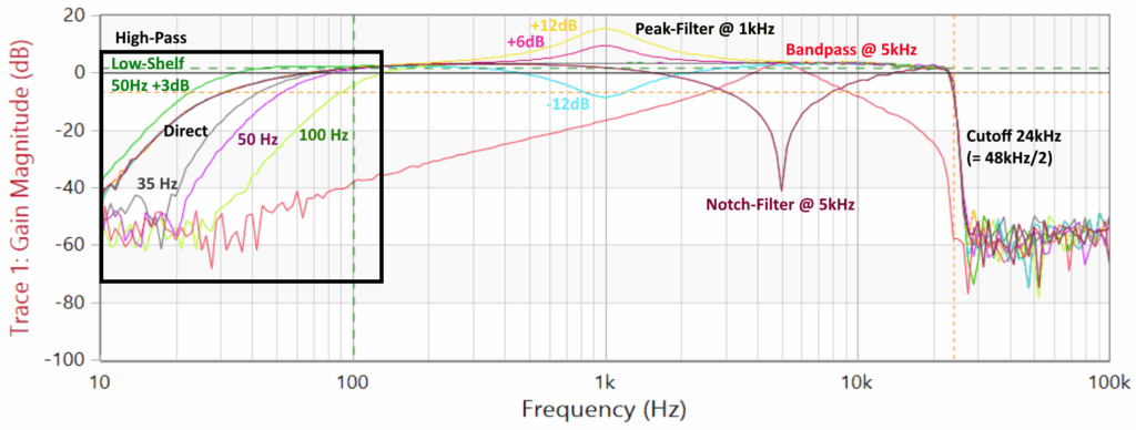
end if; That’s it. After 7 clocks, we are back in the idle-state and ready to receive the next audio-sample. With an FPGA-clock of 100MHz this means only 70ns for the calculation of this IIR-filter. While having the total available logic in mind, we can concatenate individual IIR-filters to build up a whole parametric equalizer with 5 or more individual setpoints. With the six individual coefficients we are then able to create several different audio-filters:
| Common | Special |
|---|---|
| Peak | Notch |
| High-/Low-Shelf | Bandpass |
| High-/Low-Pass | Allpass |
Crossover with steeper slope
Using these six coefficients results in the already mentioned Biquad-IIR-filter, which are filters of second-order with 12dB/octave. This is fine for general equalizing, but if you want to separate the lows for a subwoofer from the highs for the tweeters, this will produce a +3dB gain at the transfer-point if both filters are set to the same frequency. So, Siegfried Linkwitz and Russ Riley developed a new type of filter as an improved Biquad-filter: the Linkwitz-Riley-Filter. Fourth-order Linkwitz–Riley crossovers (LR4) are probably today’s most commonly used type of audio crossover. They are constructed by cascading two 2nd-order filters. Both filters can be combined in one single VHDL-block while increasing the number of coefficients:
port (
    clk         :   in std_logic := '0';
    sample_in   :   in signed(23 downto 0) := (others=>'0');
    sync_in     :   in std_logic := '0';
    rst         :   in std_logic := '0';

    -- coefficients have to be multiplied with 2^fract_bits before
    a0          :   in signed(coeff_bits - 1 downto 0);
    a1          :   in signed(coeff_bits - 1 downto 0);
    a2          :   in signed(coeff_bits - 1 downto 0);
    a3          :   in signed(coeff_bits - 1 downto 0);
    a4          :   in signed(coeff_bits - 1 downto 0);

    -- coefficients have to be multiplied with 2^fract_bits before
    b1          :   in signed(coeff_bits - 1 downto 0);
    b2          :   in signed(coeff_bits - 1 downto 0);
    b3          :   in signed(coeff_bits - 1 downto 0);
    b4          :   in signed(coeff_bits - 1 downto 0);

    sample_out  :   out signed(23 downto 0) := (others=>'0');
    sync_out    :   out std_logic := '0'
);Not only the number of coefficients has now increased, but the nescessary resolution for the multiplication, too. Using a resolution of at least 40-bit is suggested. The resultion equation is an enhanced version of the previous equation:

The additional multiplications will increase the overall calculation-time: instead of 70ns at 100MHz, the fourth-order Linkwitz-Riley-filter will now take 11 states, so 110ns in total for a mono-channel. Two or three channels can be calculated at the same time, which gives us a good compromise between logic-demand and usage of DSP-slices. If you like, you can have a deeper look at the full-featured crossover-filter at my Audioplayer-project at GitHub: filter_lr24_crossover.vhd
Calculation of the coefficients
If you do not like to use the online-Biquad-Calculator each time you want to adjust your EQ, there is a better way. I implemented the calculation of the individual coefficients in the ESP32 of the Vidor 4000. The only parameters I have to select are:
- Type of EQ
- Frequency
- Gain
- Q-Factor
For a simple peak-filter the general calculation looks like this:
void recalcFilterCoefficients_PeakFilter(struct sPEQ *peq) {
    double V = pow(10.0, fabs(peq->gain)/20.0);
    double K = tan(PI * peq->fc / audiomixer.sampleRate);
    double norm;
    double coeff_a[3];
    double coeff_b[3];

    // check if we are attenuating or boosting this frequency
    if (peq->gain >= 0) {
        norm = 1.0 / (1.0 + 1.0/peq->Q * K + K * K);
        coeff_a[0] = (1.0 + V/peq->Q * K + K * K) * norm;
        coeff_a[1] = 2.0 * (K * K - 1.0) * norm;
        coeff_a[2] = (1.0 - V/peq->Q * K + K * K) * norm;
        coeff_b[1] = coeff_a[1];
        coeff_b[2] = (1.0 - 1.0/peq->Q * K + K * K) * norm;
    }else{
        norm = 1.0 / (1.0 + V/peq->Q * K + K * K);
        coeff_a[0] = (1.0 + 1.0/peq->Q * K + K * K) * norm;
        coeff_a[1] = 2.0 * (K * K - 1.0) * norm;
        coeff_a[2] = (1.0 - 1.0/peq->Q * K + K * K) * norm;
        coeff_b[1] = coeff_a[1];
        coeff_b[2] = (1.0 - V/peq->Q * K + K * K) * norm;
    }

    // convert to Q30-format
    for (int i=0; i<3; i++) {
        peq->a[i].s32 = coeff_a[i] * 1073741824; // convert to Q30
        peq->b[i].s32 = coeff_b[i] * 1073741824; // convert to Q30
    }
}The calculation of the other types of filters are slightly different. The full source-code is available in the Audioplayer-Repository at GitHub. In the file Mixerengine.ino you will find the function “recalcFilterCoefficients_PEQ(…)” where all different types of Biquad-Filters are calculated. Furthermore, you will find the calculation of a 2nd-order Linkwitz-Riley-Filter in the function “recalcFilterCoefficients_LR12(…)” and the 4th-order LR24 in the function “recalcFilterCoefficients_LR24(…)”
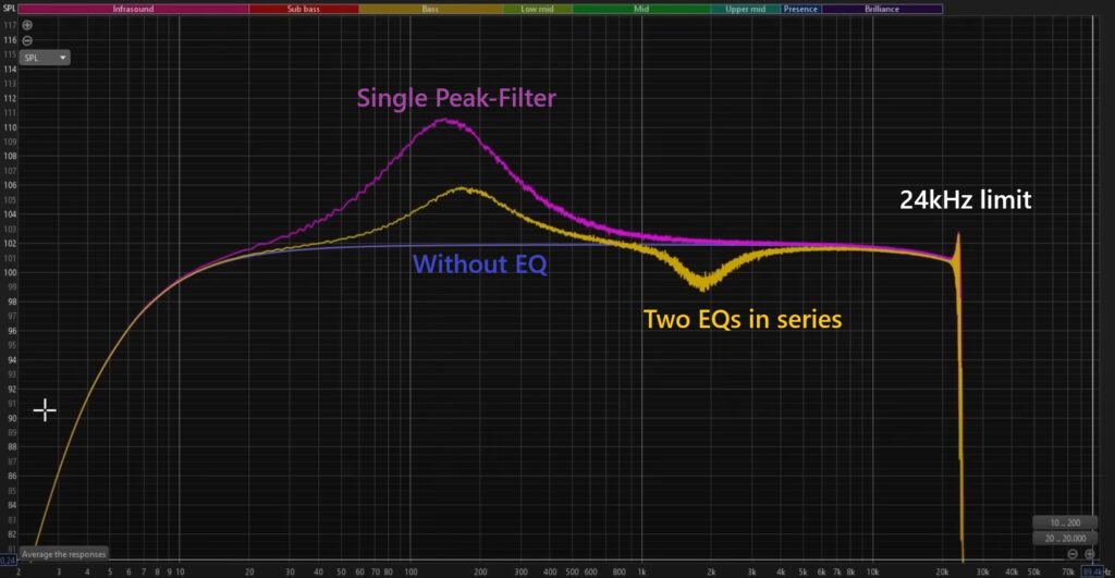
Tests
At the university I have access to several high-level-devices. For my first tests, I used an Omicron Bode 100 Analyzer connected to both the input and output of the Cyclone 10 LP and measured the frequency-response (see the featured picture of this blog-post). As this device costs around 5000,-€ there is a better and free solution if you do not own such a device: download and install the Room EQ Wizard (REW) Software. This software is intended to analyze and measure the frequency-response of a whole room using a reference-measurement-microphone. But nobody stops you from not putting a mic in the audio-path, but only an audio-device directly. So the REW-software will not measure the frequency-response of the room, but only of our device-under-test. Here you can see two different overlayed frequency-responses using a test-signal without an EQ (blue) and with an EQ (yellow):
You can find more files in my GitHub-repositories, especially the Audioplayer with EQ, or the Elektor article about the FPGA-based Audioplayer with Equalizer