Implementing an audio-compression-algorithm in pure logic is a bit challenging as it uses a division. Time for some deep-diving into audio DSP with VHDL.
Background
As I've started implementing logic for the FPGA-Audiomixer, first I had not planned to implement more enhanced audio-functions. My primary goal was to understand how a volume-control could be done using multiplying a volume-signal with the individual audio-samples. But after this was working better than expected, I pondered how the more enhanced audio-functions could be implemented. As an audio-compressor has to compare the current audio-level with a reference-level and calculate a control-signal with attack- and release-times, the calculation is a bit more challenging.
What do audio-compressors do?
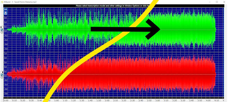
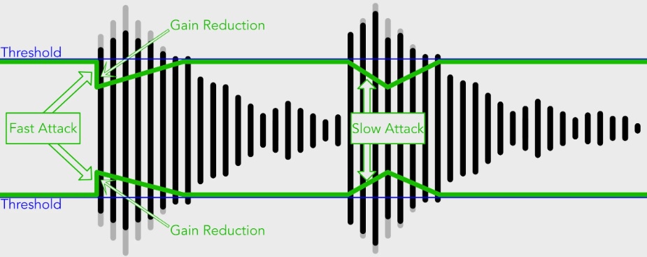
Having a look at the top-picture of this blog-article, you can see what an audio-compression is doing: louder parts of the audio are reduced while more silent parts are increased in volume. The algorithm is continuously comparing the audio-signal with a given threshold-signal. If the volume is above the threshold, the signal is attenuated with respect to the ratio. A limiter, for instance, has an infinitive ratio so that no volume can get above the threshold, while a compression with a ratio of 2:1 is less aggressive.
When the compressor is active, the overall volume is attenuated. With the makeup-gain we can increase the volume again and we will get a more dense audio-signal which can be seen visually, too (again, see the picture above).
Inputs and Outputs of an audio-compressor
OK, first lets have a look at the input- and output-signals to understand the connection to our remaining audio-mixer: we have the clock for the logic, the audio-sample and a synchronisation-input. As outputs we have the audiosample-output, a synchronsiation-output and an indication, if the compressor is doing something. The other signals are for controlling the compressor:
- threshold
- ratio
- makeup-gain
- Coefficients for attack, hold and release
port (
    clk             :   in std_logic := '0';
    sample_in       :   in signed(bit_width - 1 downto 0) := (others=>'0');
    sync_in         :   in std_logic := '0';

    -- threshold with bitdepth of sample, that will be used to check the audio-level (between 0 and 8388608)
    threshold       :   in unsigned(23 downto 0) := (others=>'0');
    -- ratio of gain-reduction (0=1:1, 1=2:1, 2=4:1, 3=8:1, 4=16:1, 5=32:1, 6=64:1, ...)
    ratio           :   in unsigned(7 downto 0) := (others=>'0');
    -- makeup-gain. (0=x1, 1=x2, 2=x4, 3=x8, 4=x16, 5=x32, 6=x64, 7=x128, 8=x256, ...)
    makeup          :   in unsigned(7 downto 0) := (others=>'0');
    -- Q15-format, 1 bit sign, 0 bit for integer-part, 15 bit for fraction-part
    coeff_attack    :   in signed(15 downto 0);
    -- 16 bit value for hold_counter = 0...65535/48000 [0...1365ms]
    hold_ticks      :   in unsigned(15 downto 0) := (others=>'0');
    -- Q15-format, 1 bit sign, 0 bit for integer-part, 15 bit for fraction-part
    coeff_release   :   in signed(15 downto 0);

    sample_out      :   out signed(bit_width - 1 downto 0) := (others=>'0');
    sync_out        :   out std_logic := '0';
    comp_out        :   out std_logic := '0'
);
So, while the threshold gives us the information about the "volume" of when the compressor has to do something, the ratio is the value of how hard the compressor has to have an effect. The makeup is simply a static gain. Furthermore, the coefficients define how fast and how long the compressor has to have an effect.
General calculation and state-machine
Looking at the following two equations, the sample at the output of our compressor is "simply" the input-sample multiplied by a gain. However this gain is a bit more complex than a simple volume-control:
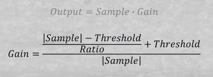
We have to calculate different things:
- Absolute value of the input-sample
- a subtraction
- a first division
- a sum
- and a second division by the absolute value again
While sums and subtractions are no big deal in pure logic and even multiplications can be done using dedicated DSP-multipliers within the FPGA, a division is much more difficult...
Division in VHDL
Looking at the following diagram created by Udayan Patankar, you can see that there are lot of different approaches calculating the division of two numbers:
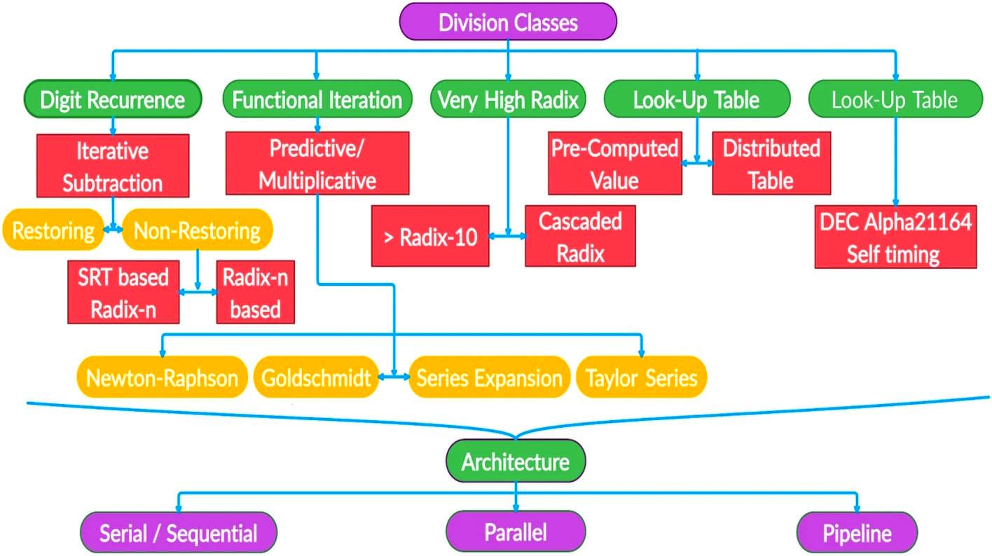
For the implementation within VHDL I've chosen an SRT based Radix-2-division. Thankfully, Lothar Miller published a Radix-2-division in VHDL on his website. I imported this algorithm as a component in my logic:
component divider is
    port (
        clk         : in   std_logic;
        start       : in   std_logic;
        dividend    : in   unsigned(23 downto 0);
        divisor     : in   unsigned(23 downto 0);
        quotient    : out  unsigned(23 downto 0);
        remainder   : out  unsigned(23 downto 0);
        busy        : out  std_logic
    );
end component;
Within the VHDL-code I'm now able to pass the individual signals to the component:
div : divider
port map(
    clk => clk,
    start => div_start,
    dividend => div_dividend,
    divisor => unsigned(sample),
    quotient => div_quotient,
    remainder => open,
    busy => div_busy
);
As the division will take several clocks, we will use the busy-signal to wait for the division-algorithm to succeed until we proceed with the remaining steps.
General state-machine
As the compressor has multiple states, I had to implement a matching state-machine for this. When a new audio-sample reaches the block and triggers the synchronisation-input, we have to check if the level is above the threshold. This will decide if we have to go into attack-mode, stay in active-mode or wait during the hold-state. If the volume is below the threshold and the hold-time is over, it has to release the compressor:
if rising_edge(clk) then
    if (sync_in = '1' and s_SM_Main = 0) then
        -- copy signals from input to local variables
        -- calculate absolute value of input-sample and put signals to division-component
        div_start <= '1';
        -- go into next state
    elsif (s_SM_Main = 1 and div_busy = '0') then
        -- load corresponding coefficient for attack, hold or release
        -- goto next state
    elsif (s_SM_Main = 2) then
        -- calculate gain * coeff
        -- goto next state
    elsif (s_SM_Main = 3) then
        -- calculate low-pass-filter
        -- goto next state
    elsif (s_SM_Main = 4) then
        -- calculate sample * gain
        -- goto next state
    elsif (s_SM_Main = 6) then
        -- set output and sync-signal
    elsif (s_SM_Main = 7) then
        -- reset sync-signal
        -- goto idle-state
    end if;
end if;
As you can see, the first state will only start, if the division has finished. Depending on the chosen clock-speed and sample-value, it will take several 10-nanoseconds to complete the division.
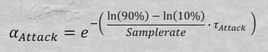
In my design I used a simple first-order low-pass-filter to control the attack and release-behaviour of the compressor. Depending on the current state, the attack-coefficient will be set accordingly:
With these tools we have everything we need for the real implementation. In 2019 the guys from Mastering the Mix have published a nice diagram how an audio-compressor is working:
In the Cyclone 10-FPGA I used a 100MHz clock for calculating the whole logic. As the compressor takes in total 7 steps, it takes 70 nanoseconds from an incoming sample to a valid output. The division will take another 24 steps, so in the end, the whole compressor is calculated within 100 nanoseconds. The time between two samples at 48kHz is 20.83 microseconds - we stay within a single sample!
Calculating the coefficients
The shown attack-, hold- and release-coefficients can be calculated within a standard microcontroller. For the sake of usability, I as a user sets these values in milliseconds, but the FPGA has no clue about milliseconds, only about samples. So I had to convert the time-information to number of samples (in case of the hold-time) or the value "tau", shown in the equation above using the following small c-function. The struct "sCompressor" contains all the imporant settings:
void recalcCompressor(struct sCompressor *Compressor) {
  // convert threshold in dBfs to integer-threshold with 23 bit (PCM without signed-bit)
  Compressor->value_threshold.u32 = pow(2, (Compressor->audio_bitwidth-1) + (Compressor->threshold/6.0f)) - 1;

  // convert ratio (0=oo:1, 1=1:1, 2=2:1, 4=4:1, 8=8:1, 16=16:1, 32=32:1, 64=64:1)
  // to bitshift 1:1=0bit, 2:1=1bit, 4:1=2bit, 8:1=3bit, 16:1=4bit, 32:1=5bit, 64:1=6bit, oo:1=24bit
  if (Compressor->ratio > 0) {
    // convert real ratio-values into bit-shift-values
    Compressor->value_ratio.u16 = log(Compressor->ratio) / log(2);
  }else{
    // ratio == 0 -> limiter = oo:1
    Compressor->value_ratio.u16 = Compressor->audio_bitwidth;
  }

  // we are allowing only 6dB-steps, so we have to round to optimize the user-input
  Compressor->value_makeup.u16 = round(Compressor->makeup/6.0f);

  // convert milliseconds to Q15-fixed-point
  Compressor->value_coeff_attack.s16 = round(exp(-2197.22457734f/(audiomixer.sampleRate * Compressor->attackTime_ms)) * 32767);

  // calculate milliseconds to number of samples
  Compressor->value_hold_ticks.u16 = Compressor->holdTime_ms * (audiomixer.sampleRate / 1000.0f);

  // convert milliseconds to Q15-fixed-point
  Compressor->value_coeff_release.s16 = round(exp(-2197.22457734f/(audiomixer.sampleRate * Compressor->releaseTime_ms)) * 32767);
}
Of course, thats only an overview of the most important parts of the system and a few lines of code are still missing to get a working system, but that's it in general.
It took me a couple of days to implement, test and debug this compressor but in the end the compressor was working very fine. That was a great experience when my compressor worked the first time without problems. I set it as a limiter with low threshold and a high makeup-gain and first whispered into the connected microphone then yelled at it - both had the same volume.
Noisegate and outlook
Now that I had a super-fancy and fast audio-compressor, I thought about a noisegate. As this device has to open, if an audio-sample is above a specific threshold, hold a specific amount of time and close the gate if the sample is below this threshold, the behaviour of the noisegate is comparable to the compressor. It is even simpler as there is no division nescessary. So I copied the VHDL-code for the compressor, removed the division, inverted the gain-structure to open on loud signals - and that's it. I used the same first-order low-pass to smooth the attack and release and a simple sample-counter for the hold-time.
The final implementation of both, the compressor and noise-gate, is quite efficient regarding the demand of logic. Even the Cyclone 10 LP of the Vidor4000 with around 16.000 logic-elements is able to take multiple compressors and noise-gates besides the general audio-decoding and processing.
OK, that's it for now. In one of the next articles I will pick this topic up again and write a bit about the equalizers I've implemented as IIR-filters. Thanks for reading and see you next time.
Comments