
Based on my Audioplayer-project I developed a DIY card for the Behringer X32. In addition to the youtube-video here you will find some more detailed information about this project and the implementation.
Definition of reverse-engineering by Elliot J. Chikofsky: "Reverse-engineering is the process of analyzing a subject system to identify the system’s components and their interrelationships and create representations of the system in another form or at a higher level of abstraction". This in mind I did some reverse-engineering on one of the most selled audiomixing-consoles in the world.
The Behringer X32 (including the newer products like the WING) is a very versatile eco-system with lots of products able to be interconnected by digital connections like UltraNet, AES50, USB, Ethernet, etc. So I pondered if I could connect my FPGA-based Audioplayer with mixing-abilities to this console in some way. One of the most promising connections seemed to be the expansion-card-connector. In the end this project has developed into an eldorado for implementation of different protocols and signaling technologies...
Hardware-connection
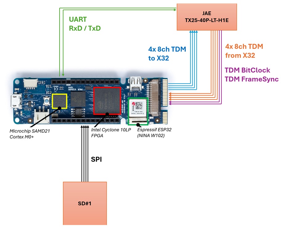
The expansion-card-connector is a TX25-40P-LT-H1E connector made by JAE. It has 40 pins and it took me a while to identify the individual pins, but the general pinout is shown in the following table:
| Row A | Row B | Row C | Row D |
|---|---|---|---|
| 1 GND | 2 GND | 21 GND | 22 GND |
| 3 GND | 4 GND | 23 TDM8 X32 Ch 1-8 | 24 n/c |
| 5 n/c | 6 n/c | 25 TDM8 X32 Ch 9-16 | 26 BitClock |
| 7 n/c | 8 n/c | 27 TDM8 X32 Ch 17-24 | 28 WordClock |
| 9 n/c | 10 GND | 29 TDM8 X32 Ch 25-32 | 30 n/c |
| 11 n/c | 12 GND | 31 TDM8 SDCard Ch 1-8 | 32 n/c |
| 13 +5V | 14 +5V | 33 TDM8 SDCard Ch 9-16 | 34 MIDI Tx X32 |
| 15 +5V | 16 +5V | 35 TDM8 SDCard Ch 17-24 | 36 MIDI Tx X32 |
| 17 GND | 18 GND | 37 TDM8 SDCard Ch 25-32 | 38 UART Rx X32 |
| 19 GND | 20 GND | 39 3V3 Card Ready | 40 UART Tx X32 |S |
As the X32 and the expansion-cards are using 3V3-signals, the connection to the Vidor4000 is pretty straight-forward. Simply connect the signals directly to the FPGA-pins is OK. On some signals I put some 330Ohm resistors as in the original X-LIVE card to limit the currents and damp oscillations.
Communication-protocols
Once the X32 has intialized the card, the four TDM-lines, bitclock- and wordclock-signals are driven by the main-console with useful signals. So first I had to implement the general communication between the expansion-card and the X32. As plain UART with 38400 baud is used, I could use a standard-communication-port of my microcontroller. The X32 sends and expects commands starting with a "*" and ending with an "#", so my receiver-function puts all received characters into a ringbuffer and searches for a new command when receiving a "#":
  if (SerialX32.available() > 0) {
    // read all characters. The individual commands can be distributed over several chunks.
    uint8_t rxChar = SerialX32.read();
    x32RingBuffer[x32RingBufferPointer++] = rxChar;

    if (x32RingBufferPointer >= X32_RINGBUF_LEN) {
      x32RingBufferPointer = 0;
    }

    // check new command on receiving "#"
    if (rxChar == 35) {
      x32SearchCmd();
    }
  }
Now that I could receive all characters into a ring-buffer, I had to write a function to search for a valid command:
// search for a valid command starting with "*" and ending with "#" and execute the command
void x32SearchCmd() {
  [...]
  // increment i beyond the limit of the buffer to catch commands around the border
  for (i=0; i<(X32_RINGBUF_LEN + 22); i++) {
    if (x32RingBuffer[x32RingBufferPointerOverflow(i)] == 42) { // search for "*"
      // we found the begin of a command
      commandBeginIndex = x32RingBufferPointerOverflow(i);

      // now search for the end of the command from the current index
      for (j=commandBeginIndex; j<(X32_RINGBUF_LEN + 22); j++) {
        if (x32RingBuffer[x32RingBufferPointerOverflow(j)] == 35) {
          // we found a possible end of command. Lets copy the data and validate the command
          commandEndIndex = x32RingBufferPointerOverflow(j);

          if (commandBeginIndex < commandEndIndex) {
            // we are in the same direction -> just copy chars
            // ____*xxxxxx#_____
            commandLength = commandEndIndex - commandBeginIndex + 1;
            memcpy(&commandArray[0], &x32RingBuffer[commandBeginIndex], commandLength);
          }else if (commandBeginIndex > commandEndIndex) {
            // we have to copy the chars around the corner
            // xxx#_________*xxx
            commandLength = commandEndIndex + (X32_RINGBUF_LEN - commandBeginIndex) + 1;
            memcpy(&commandArray[0], &x32RingBuffer[commandBeginIndex], X32_RINGBUF_LEN - commandBeginIndex); // copy first part from the end
            memcpy(&commandArray[X32_RINGBUF_LEN - commandBeginIndex], &x32RingBuffer[0], commandEndIndex + 1); // copy last part from the beginning
          }

          // convert to String, execute the command and output the Answer
          SerialX32.print(x32ExecCmd(String((char*)commandArray)));

          // set used chars from ring-buffer to 0
          for (k=i; k<(i+commandLength); k++) {
            x32RingBuffer[x32RingBufferPointerOverflow(k)] = 0;
          }
          // clear commandArray
          for (k=0; k<32; k++) {
            commandArray[k] = 0;
          }

          break;
        }
      }
    }
  }
}
The X-Card-commands itself are a bit cryptic: to select a specific session from SD-card on the X-LIVE, the command is *9Bxxxxxx#, where the x marks the session-identification. To play the selected session we have to read the command ***9D#**. The most important command we will receive from the main-console is ***8I#**. This requests for identification of the card. We have to answer with ***8X-UREC:A:12#** if we want to be an X-LIVE-card with firmware-revision A12. I put all commands I found up to now into an unofficial command-documentation at GitHub.
Audiodata
Now that the X32 recognized us as a valid X-Card, I had to implement the receiver for the 8-channel TDM-audio. I used my I2S-receiver for this task. Here you can see the input- and output-definition of the VHDL-block:
port (
    clk         : in std_logic; -- mainclock
    bclk        : in std_logic; -- bit-clock of TDM signal (for X32 it is 12.288 MHz)
    fsync       : in std_logic; -- Frame sync (for X32 it is 384 kHz)
    sdata       : in std_logic; -- serial data (8x 32 bit audio-data: 24 bit of audio followed by 8 zero-bits)

    ch1_out     : out std_logic_vector(23 downto 0); -- received audio-sample
    ch2_out     : out std_logic_vector(23 downto 0); -- received audio-sample
    ch3_out     : out std_logic_vector(23 downto 0); -- received audio-sample
    ch4_out     : out std_logic_vector(23 downto 0); -- received audio-sample
    ch5_out     : out std_logic_vector(23 downto 0); -- received audio-sample
    ch6_out     : out std_logic_vector(23 downto 0); -- received audio-sample
    ch7_out     : out std_logic_vector(23 downto 0); -- received audio-sample
    ch8_out     : out std_logic_vector(23 downto 0); -- received audio-sample
    sync_out    : out std_logic -- new data received successfully
  );
As we receive 8 24-bit samples with each 48kHz, we have to decode individual bits at a frequency of 12.288MHz as TDM uses 32-bits. So I used a 200MHz clock for the FPGA-logic to have a good enough time-resolution. The VHDL-implementation is then pretty easy: on each read bit, I increment a bitcounter and on the rising edge of the wordclock I put all received data to the output-signals:
if rising_edge(clk) then
    zbclk <= bclk;
    zzbclk <= zbclk;
    zzzbclk <= zzbclk;

    if (zzbclk = '1' and zzzbclk = '0') then
        -- rising edge of bitclk
        zfsync <= fsync;

        -- continuously reading bit into shift-register
        if ((bit_cnt >= 0) and (bit_cnt <= 31)) then
            ch1 <= ch1(ch1'high - 1 downto 0) & sdata;
        elsif ((bit_cnt >= 32) and (bit_cnt <= 63)) then
            ch2 <= ch2(ch2'high - 1 downto 0) & sdata;
        elsif ((bit_cnt >= 64) and (bit_cnt <= 95)) then
            ch3 <= ch3(ch3'high - 1 downto 0) & sdata;
        elsif ((bit_cnt >= 96) and (bit_cnt <= 127)) then
            ch4 <= ch4(ch4'high - 1 downto 0) & sdata;
        elsif ((bit_cnt >= 128) and (bit_cnt <= 159)) then
            ch5 <= ch5(ch5'high - 1 downto 0) & sdata;
        elsif ((bit_cnt >= 160) and (bit_cnt <= 191)) then
            ch6 <= ch6(ch6'high - 1 downto 0) & sdata;
        elsif ((bit_cnt >= 192) and (bit_cnt <= 223)) then
            ch7 <= ch7(ch7'high - 1 downto 0) & sdata;
        elsif ((bit_cnt >= 224) and (bit_cnt <= 255)) then
            ch8 <= ch8(ch8'high - 1 downto 0) & sdata;
        end if;

        -- check for positive edge of frame-sync (1 bit-clock before bit 0 of channel 1)
        if (fsync = '1' and zfsync = '0') then
            -- rising edge of sync-signal
            ch1_out <= ch1(31 downto 8);
            ch2_out <= ch2(31 downto 8);
            ch3_out <= ch3(31 downto 8);
            ch4_out <= ch4(31 downto 8);
            ch5_out <= ch5(31 downto 8);
            ch6_out <= ch6(31 downto 8);
            ch7_out <= ch7(31 downto 8);
            ch8_out <= ch8(30 downto 7); -- in this step we are missing a single bit
            sync_out <= '1';

            bit_cnt <= 0;
        else
            bit_cnt <= bit_cnt + 1;
        end if;

        if (bit_cnt = 4) then
            -- reset sync_out
            sync_out <= '0';
        end if;
    end if;
end if;
The VHDL-code for sending 8-channel audio-data back to the X32 is using a very comparable logic. The whole code can be found in the GitHub-project.
Controls
As I wanted to use this extension-card for some of my gigs on stage, I tried to implement some controls in addition to the WiFi-webinterface. The first idea was to add some ethernet-controls using another self-developed app. But while looking at the ethernet-protocol for the original X32-Edit I decided to support this XRemote-protocol as it is based on the OSC-protocol. Once I figured out how to initiate the communication and the X32-Edit-software displayed my card as a valid endpoint, most of the work was comparing and interprating ASCII-strings. The "address" of the data is sent in plain ASCII, while the value is sent as 32-bit integer- or float-value:
// /ch/xx/mix/fader~~~~,f~~[float]
// /ch/xx/mix/pan~~,f~~[float]
// /ch/xx/mix/on~~~,i~~[int]
channel = ((rxData[4]-48)*10 + (rxData[5]-48)) - 1;
if (len > 13) {
if ((rxData[7] == 'm') && (rxData[8] == 'i') && (rxData[9] == 'x')) {
  if ((rxData[11] == 'f') && (rxData[12] == 'a') && (rxData[13] == 'd')) {
    // get fader-value
    value32bit.u8[0] = rxData[27];
    value32bit.u8[1] = rxData[26];
    value32bit.u8[2] = rxData[25];
    value32bit.u8[3] = rxData[24];

    float newVolume = (value32bit.f * 54.0f) - 48.0f;
    mixerSetVolume(channel, newVolume);
Now that the XRemote was working I had a look at the XTouch-controller. As I said, this project has developed into an eldorado for implementation of different protocols. Different to the XRemote-protocol, the XTouch-device uses up to 300-byte-long UDP-commands over ethernet. But some of the commands are really simple: to update the main-fader-position, for instance, I had to send a simple 3-byte-command as the communication is leaning on a general MIDI-communication:
uint8_t XCtl_TxMessage[3];
uint16_t faderPosition;
XCtl_TxMessage[0] = 0xE8; // E8=Masterfader
XCtl_TxMessage[1] = faderPosition & 0x7F; // MIDI-Values between 0 and 127
XCtl_TxMessage[2] = (faderPosition >> 7) & 0x7F;

if (XCtlUdp.beginPacket(XCtl.ip, 10111)) {
  XCtlUdp.write(XCtl_TxMessage, 3);
  XCtlUdp.endPacket();
}
After several days I figured out how to implement all faders, the meters, knobs and LC-displays of the device. In the current state of this projects up to 4 XTouch-devices are supported at the same time.
As all XTouch-functions were working as expected I realized, that the MackieMCU-protocol is very comparable to the XTouch-protocol. As one of the youtube-commenter suggested to support the DAW-option of the X32, this was the right time to implement this MackieMCU-protocol as I already connected the MIDI-Rx/Tx to the Vidor 4000. After a couple of hours the X32 showed text from my expansion-card:

As I had plenty of space left in the SAMD21 controller, I implemented some DMX512-controls next to the audio-mixing-functions. So it is possible to control the stage-lights from the X32-surface simply by pressing the "REC" button to switch between audio and DMX512.
In the end a lot of different control-schemes have been implemented for this DIY card:
- a WiFi webinterface (based on the ESP32)
- Ethernet-control using plain ASCII-commands
- control via the X32-surface using MackieMCU emulation
- Ethernet-control using Behringers X32-Edit or the Android-App (XRemote)
- Ethernet-control using XTouch-control
Test of the card
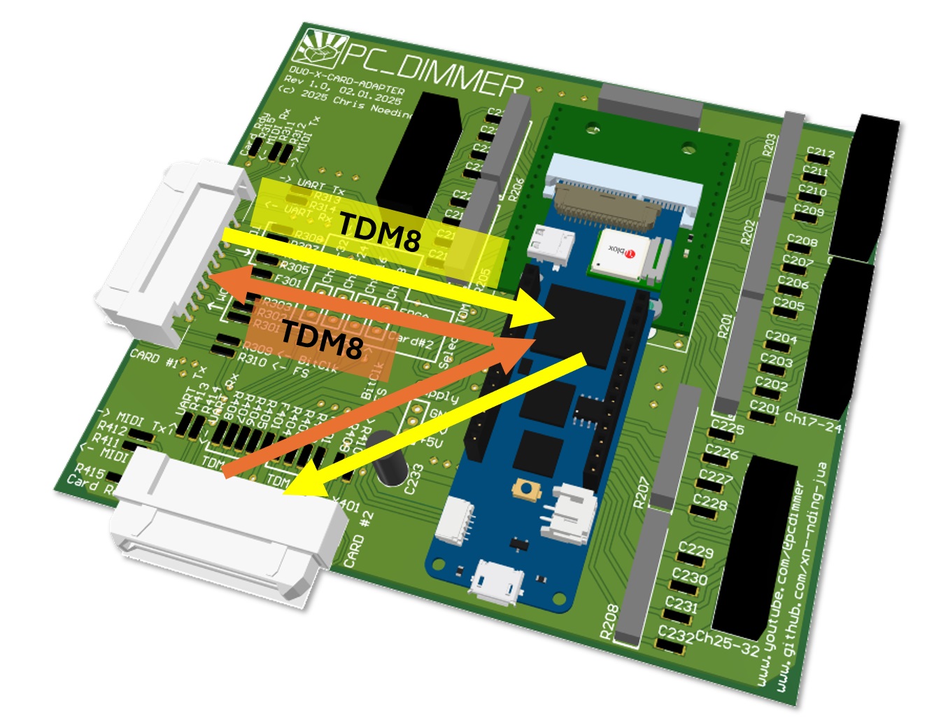
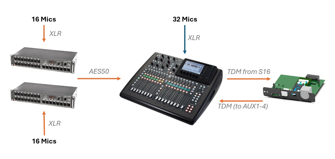
In the last days of 2024 I've developed a card to connect two Expansion-Cards. I added 32 individual RC-LowPass-Filters on this card to be used as a Digital-2-Analog-Converter as well. So I used this card to initialize an X-LIVE-Card to output 32 analog-signals to my main-console that were routed to my DIY-Expansion-Card. Together with the 32 audio-signals in the original processing this resulted in a total of 64 audio-channels processed by the X32. You can find the software and PCB information on GitHub as well:
GitHub-Repository of DuoXCardAdapter
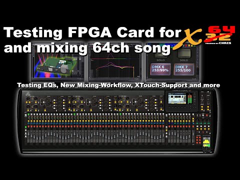
The results of the card-tests can be found on Youtube:
Summary
As you may have realized, I love projects that implements a lot of different functions, that are a combination of hard- and software. This DIY expansion-card was a perfect example for this: initially started as a proof-o-concept, this card developed into a versatile and universal control option with additional audio functions.
It was lot of fun programming this piece of hardware. As this card is designed for a hardware initially published in 2012, I'm now working on an expansion-card for the Behringer WING, but this is a topic for another blog-post.
Comments