Plug&Play is a mystery to you? Until recently it was for me too, but let's take a look at the PCI specifications and lift the fog of mystery about PnP.
Plug&Play
Christmas 1994 my family and me got the first computer: an Intel 486Dx4-100 with 16MB RAM and a 534MB harddisk-drive. The only expansion-card was a SPEA V7 VegaPLUS PCI VGA-card. No sound, no CD-ROM, no ether- or internet. Windows for Workgroups 3.11 worked flawlessly with a razor-sharp 800x600 resolution on our 14" CRT-monitor.
A couple of months later my brother and me added a sound-card to the system and the BIOS showed us some information about the card - we were thrilled about this device-recognition but had to install the drivers manually. One year later in the end of 1995, we installed Windows 95 on this machine and magically Windows installed both, the graphics-card and the sound-card automatically. But how? For me these developers, that could create such magic software to detect the hardware, were heros. 30 years later I'm an electrical engineer and it was just about time to understand how the basics of computer-expansioncards work...
Hardware playground
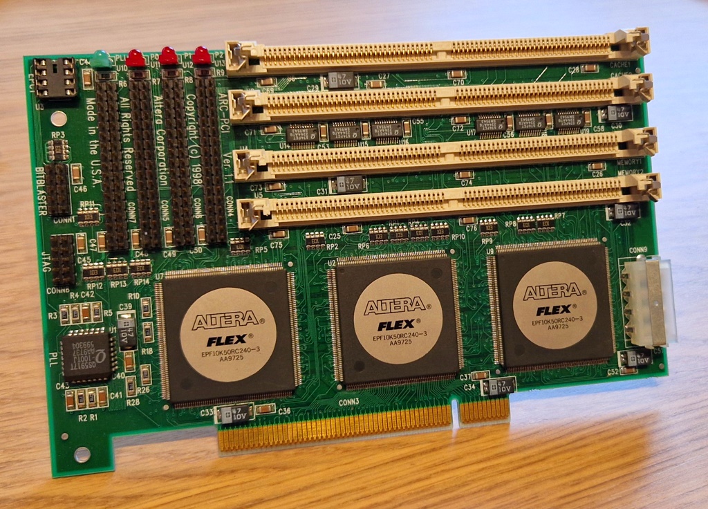
Just reading specifications is not enough for me. Searching around on eBay I found a promising old PCI-card for some tests: the Altera ARC-PCI in revision 1.1. This card consists of three Altera FLEX10K devices, that are Embedded Programmable Logic Devices (PLD). These chips have been developed in 1996 and can handle clock-speeds of up to 125MHz - pretty impressive for 1996. One of the FLEX10K is connected to the PCI-connector and is able to handle the 5V logic directly. So this is a wonderful hardware-basis for some tests - besides the fact that there were no other comparable cards available on eBay at this time.
The card arrived in good condition, but unfortunately there was no documentation available. From my musle-memory I opened Google.com and searched for "Altera ARC-PCI"... but wait... I only got results about Intels ARC-Graphics card, Alteras PCI-Express reference-design, two papers on IEEE-Explore and some old "News" from 1997 - no information about the ARC-PCI, its pinout or something helpful. After couple of hours searching I come to the conclusion, that "The internet never forgets" is not valid for pages before the 2000s. Even using the Wayback-Machine offered only some general information about the card, but no specific documentation.
Ok, I thought to myself, lets contact the Intel/Altera-guys for some help - I'm only searching for a PDF containing a pinout, right? A short eMail to my contact at the company and only a couple of hours later I got a response: "Hi Chris, unfortunately, I have no information about this old treasure" - bummer.
Reverse engineering
The only option was the reverse-engineering of the card. So I made pictures from the front and back of the PCB, overlayed them in Paint.Net and tried to figure out the individual connections between the PCI-connector and the PLD in the center:
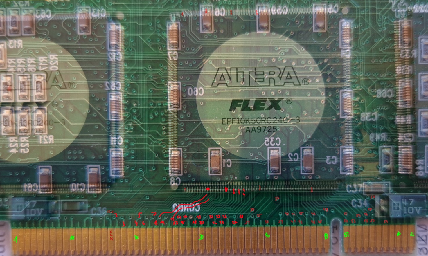
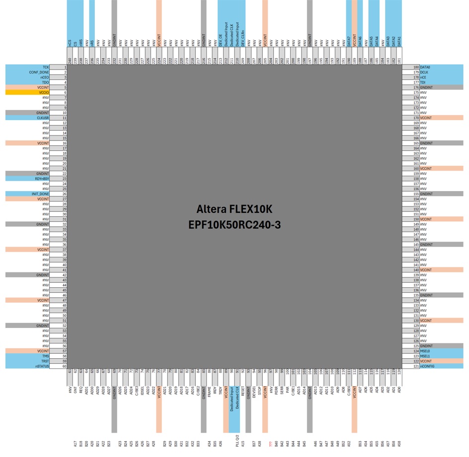
In the end I figured out all of the important PCI-pins. Up to now I didn't put effort into backtracing the tracks between the individual FLEX10K and the memory-moduls - this is a task for a rainy afternoon. In Excel I created my own pinout for this chip:
Modern FPGAs have PLL-modules on board, but this card has its own dedicated PLL-chip. Luckily I could find the datasheet even the chip has been discontinued in 2014: it is a Renesas QS5917T low-skew CMOS-PLL:

As the PCI-clock with 33MHz is connected to the input, the individual outputs Qx of the PLL are connected to the individual PLD-chips. The FLEX10K which is responsible for the PCI-communication is connected to Q0 (33 MHz) and Q/2 (16.5MHz). With this knowledge, I was ready to dive into the PCI-specifications as the hardware is ready for some logic...
PCI-specifications
The first PCI-specification has been published in 1992. As my card is from 1998, I searched for a newer revision and found the PCI-specification in version 2.2 from 1998. Looking into the spec I found the important section that holds the information for Plug&Play: the configuration space. Within this 256 byte area, the card provides important information to the PCI-host and the first 16 bytes are the most important for PnP:
| Bits 31 downto 16 | Bits 15 downto 0 |
|---|---|
| PID | VID |
| Status | Command |
| ClassCode | ClassCode/RevID |
| BIST / Headertype | Latency Timer / Cache Line Size |
So with the VID and PID we can define what type of card we want to build-up. The BIOS is reading the first bytes and show the information in the boot-up-table. Windows from Win95 onwards uses this information to identify the specific card and select the driver for it - somewhat disillusioning, but that's the whole magic..
Implementing some logic
With the configuration-space of the PCI-specification in mind, I had to implement some logic, so that the PCI-host can read this data. Next to the Address-/Data-Lines (32-bit) there is a 4-bit-wide command-/byte-enable signal. The minimum command-set for a usable PnP-card is:
- confread
- confwrite (even if not used)
- iowrite
- ioread
As the address-/data-lines are used for both, reading and writing, I had to configure the pins of the FLEX10K as bidirectional. Looking at the signal-diagram down below, the general process needs a small state-machine:
- Wait for an asserted nFRAME signal
- check IDSEL: if high, we are in configuration-space-mode
- read address (a DWORD-address of config-space while first two bits must be "0") and check command on asserted nFRAME
- if command is config-read: turnaround the pin-direction on next clock-cycle
- write desired config-space data on falling-clock-edge to AD-lines
- done
Looking at the signals you can see, that we have to take care of the nIRDY, nTRDY and nDEVSEL-signals as well:

Taking care of all four commands and the additional signals, it took around 350 lines of VHDL and 9% of the overall logic-elements of the FLEX10K for the PCI-target logic. The Quartus 9-project now looks like this:

Outlook
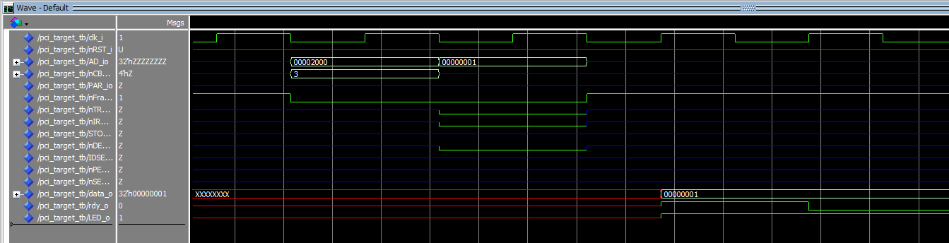
The general preparations for the PCI-card are done and a first logic is ready. Within the simulation the communication is looking promising already. In the following diagram an I/O-Write is performed at IO-Address 0x2000. The data contains only a "1" to turn on an LED. On the first clock with asserted nFRAME, the PCI-target reads its own address "0x2000" and the command (here 0x03 = iowrite). On the falling edges the target tells the host, that it is ready to receive data. On the next rising edge of the clock the PCI-host sends the data, here a 0x00000001 and the data is set to the LED output on the following edge:
In the next step the card will be tested in my Pentium MMX 233MHz system using Windows 95. You can find more information in the FPGA-PCI-Card GitHub-project. I'm not really sure what I will do with this prototyping card in the end. Some ideas:
- basic UART-transceiver
- DMX512-sender
- aquisition-card for an external ADC
- audio-interface-card with basic DSP-functions using the other two FLEX10K devices
If the first tests were successful, more about the software-development and what I will do with this card, you can find out in a follow-up blog-post...
Comments